Articles
Crystal set
- The Crystal Set
- The Crystal Detector Circuit
- The Hook-Up or Circuit
- Circuit With Coupler
- Difficulty with Selectivity
- Picture Diagram of Set
The Crystal Set
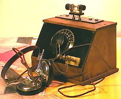 The crystal set has always seemed the most wonderful of all radio receivers, for with this device we employ the feeble energy of the radio waves alone to vibrate the diaphragms of the phones without aid or reinforcement from local sources of energy. After traveling many miles, there is still sufficient energy left in the waves to move a relatively stiff piece of metal and to produce the audible air vibrations known as sound. Further, it is an exhibition of the remarkable sensitivity of the headset which produces understandable signals on so small an amount of current that it can be estimated in millionths of an ampere; and yet, with all of this delicacy, the apparatus is perfectly simple and so rugged that it can withstand a considerable amount of abuse at the hands of the listener.
To most of our readers who have had experience only with the cheap and simple single-slide, single-circuit crystal detector sets sold on the open market, the crystal detector is considered only in the light of a toy having only a very limited use in reception. This, however, is not the case, for with proper attention to the details of construction and with as much care taken with the tuning units as we pay to the construction of a tube set, the performance can be greatly improved in regard to distance range and signal strength. If we constructed our tube sets with the same lack of care and with the same primitive tuning systems that are used on commercial crystal sets, we would not get very much better performance. Single-slider, single-circuit tuners are not conducive of good results with either the crystal or tube detector, for they cannot be tuned accurately in resonance with the incoming waves, and there is always a considerable loss taking place that limits the distance and volume.
The Crystal Detector Circuit
Our primitive crystal detector circuit consists of three principal units: (1) The tuning unit, by which it is brought into resonance with the incoming waves, (2) The crystal detector employed for rectifying the radio frequency impulses for the development of the audio waves, and (3) The audio output mechanism which converts the audio frequency electrical waves into mechanical sound vibrations (Phones). All three elements must be as perfect as possible if we are to extract the maximum output in the form of sound, for the incoming energy is exceedingly weak and must be carefully utilized with the least possible loss. This means sharp tuning, a crystal having excellent rectifying qualities and an exceedingly sensitive pair of phones, none of which are in evidence in the usual $10.00 crystal detector set. In reviewing the requirements, we must also remember to include an efficient antenna into the assembly, which should have greater length and capacity than the antenna commonly used with tube sets. The latter item is generally neglected in the installation of a crystal set, with the result that very little volume or distance is had. Conservation of energy is a prime requisite.It is here that the low-loss coil and the low-loss condenser hold forth with particular advantage; spiderweb, honeycomb or barrel-wound coils being of great advantage in the construction of such a set. The phones should preferably be of the mica diaphragm class or with very thin flexible metal diaphragms so that the slightest current in the coils will give a maximum vibration. When we look at the cheap phones ordinarily supplied with crystal sets,with their thick cast-iron diaphragms and their weak magnets, it is no wonder that reception is limited to 10 or 15 miles. This would be almost the case with a tube set if it were supplied with the same sort of phones. The feeble impulses received demand the most sensitive and efficient equipment that we can supply if the crystal set is to be more than a mere toy for children's use.
Please don't infer that I am recommending the crystal set as a substitute for the tube set, for I am not. I am simply bringing to your attention the fact that the crystal set performance can be wonderfully improved by a little care in the construction and that it is a most desirable proposition for local reception where we do not wish to go to the trouble of installing batteries or using the electric outlet. The crystal set is in field all its own and is almost indispensable for certain purposes, and for this reason I believe that more attention should be paid to the development of its performance rather than to cutting down on the expense of construction, as has been done heretofore. You cannot get long distance consistently, nor can you get full loud speaker volume of the crystal alone, but you can get local stations with good volume, clear and sweet, without the fuss attending the operation of a tube receiver.
When loud speaker volume is required on local, with particular attention to quality, we can add one or more stages of audio frequency amplification to the detector. Of course, we are now getting back to vacuum tube complications and batteries or other power, but with very simple layouts we can obtain wonderful tone values on the loud speaker and a somewhat increased distance. Just as an experiment, it is very interesting to add resistance coupled stages to a crystal detector to discover what real tone purity is like. The natural tone and life-like quality will be a revelation to you, and if you live within 25 miles or so of a broadcasting station, I am sure that you will keep the crystal set hooked up permanently
While the complete theory of contact rectification is not well understood. I will explain the functioning and purpose of the crystal in a general way so that the beginner can at least get a working knowledge of its properties when installed in the receiving set. mechanically it is very simple, consisting of a small piece of mineral called the crystal, and a thin wire making light contact with the crystal at a sensitive spot. In some cases, the contact is made between two crystals instead of between the wire and crystal, but in any event the radio frequency current must pass through a high resistance contact of some sort before passing through the phones, so that the audio or "hearable" portion of the incoming waves can be developed.
Owing to the rapidity with which the radio wave oscillates back and forth, the diaphrams of the earphones cannot follow the radio frequency currents in the receiver directly and nothing will be heard in the phones if some sort of rectifier or "detector" is not inserted into the circuit.
These waves are "alternating," that is they flow first in one direction and then in the other, and before we hear the signals these waves must be made "unidirectional" so that they will flow in one direction through the phones but with an intensity that varies according to the sounds sent out by the broadcasting station. The crystal detector with its contacting "catwhisker" wire acts as such a rectifier and permits the passage of waves that are flowing in the same direction.
With the higher radio frequency current rectified, the "audio frequency" waves are made usable and developed so that the diaphragms of the phones follow the slower voice or music frequency pulsations, thus producing sound. Radio station waves therefore consist of two components, the high radio frequency carrier waves oscillating at the rate of about 1,000,000 vibrations per second, and the audio frequency waves impressed on them that will range from a few hundred to an upper limit of about 17,000 vibrations per second. These latter waves are produced by varying the intensity of the radio waves by "modulation," and are not actually an independent series.
There are a great number of minerals that will act as detectors to some extent, but only a few that are effective enough to be used in the practical crystal set. Galena, silicon, carborunduni, cerusite pyrites, perikon, radiocite, and hecite are among the most commonly used simple minerals, and in addition to these are the numerous synthetic crystals that bear a multitude of trade names. A good galena crystal is probably one of the most sensitive crystals, but it is not stable and must be readjusted frequently. Silicon and carborundum do not require so frequent adjustment and are quite sensitive if carefully selected and mounted. The synthetic crystals are in most cases stable and sensitive, and have the advantage ot having a greater effective area or more "hot spots" than the natural crystals, so that it is not so difficult to adjust them.
For the catswhisker wire, we require a metal that will not corrode under ordinary atmospheric conditions and one that will maintain a bright metallic contact area at the point where it rests on the crystal. A copper wire will do well with most crystals, but a silver or gold wire is better, as it does not corrode or get dull as rapidly. With the exception of the carborundum crystal, the catwhisker wire should make very light contact with the crystal, working best when only just barely touching the surface. With the carborundum detector a very heavy pressure is required, which in itself is one reason for the stability of capacitance temperature coefficient carborundum, as the heavy pressure prevents the displacement of the contact when subjected to vibration.
There has been a great deal of argument for and against the fixed crystal detector with the immovable catwhisker, but I believe that the fixed detector will prove best in the long run for the beginner, at least, as it avoids the necessity of constant readjustment and the detuning effect when these adjustments are made. It will perhaps be of interest to know that the crystal has a great deal of effect in the tuning of the circuit and very often we can tune a station in and out by means of the crystal adjustment alone. For the experienced crystal set operator, the adjustable crystal is therefore often an advantage, as it is an aid to selectivity and tuning, particularly where there are many strong local stations and other interferences.
It is a good plan to get a number of crystals and then select the best crystal by actual test. There is a great deal of variation among crystals even of the same make and type, and the only way that you can be assured of the maximum results is to select the best crystal from a number of samples.
The Hook-Up or Circuit
There are over a thousand different crystal detector hook-ups from which to make a choice, and all of them have their adherents, who believe that they have the only circuit worth using. Some employ variometers for tuning inductances, others use spiderweb coils, variocouplers, honeycomb coils and straight solenoid coils in all sort of combinations, but as a matter of fact, a close examination will show that most of these circuits can be boiled down to six distinct classes.The type of inductance does not change the characteristics of a circuit as a circuit; it simply adds or detracts from its efficiency by the sharpness of its tuning properties and the losses occuring within the coil. A variometer may show better results than a simple tuning coil, for the reason that it can be more closely adjusted to wavelength than the coil. An inductance is an inductance no matter what form it may he used.
Below we will look at six basic circuits with their relative audibility value, as determined by the U. S. Bureau of Standards. (1923) The relative signal strengths are given in terms of percentages, and it will be seen that the hook-up has a great deal to do with the reception, varying as it does from 10 per cent to 85 per cent.
These diagrams refer only to the detector circuit itself and do not consider the various methods of coupling or connecting the circuit to the aerial and ground. A variable condenser is used for tuning a fixed inductance in all cases.
Diagram A

Diagram (A) shows a simple form of circuit often used, which contains the inductance (L), the variable condenser (C), the crystal detector (CD) and the phones (Ph) all connected in series. For ordinary broadcasting wavelengths there will be about 55 turns of wire in (L) when wound on a three inch tube, and the capacity of the variable condenser (C) will be from 0.00035 mf. to 0.0005 mf. The audibility is 55 per cent.
Diagram B

In Diagram (B) we have the same circuit with the addition of the small fixed condenser (K) connected across the crystal detector. This fixed condenser acts as a storage capacity for the waves and adds considerably to the volume, as it supplies an additional current to the crystal.. This addition has increased the audibility from 55 per cent to 85 per cent, the maximum value determined by the Bureau. The capacity of (K) depends upon the nature of the crystal detector, but in any event the capacity must be small to prevent by-passing much of the current across the detector. With some detectors 0.00025 mf is about right, while with other types this may be as low as 0.0001 mf. or even less. A small three-plate variable condenser will often prove of value in getting the adjustment correctly.
Diagram C

In Diagram (C) we have the same circuit as in Diagram (A), but a fixed condenser (K) is used to bypass radio frequency current around the phones. The average audibility under all conditions is reduced to 45 per cent; hence, this is not always an advisable addition. In many makes of phones there is a considerable amount of distributed capacity in the windings of the magnets and this frequently is sufficient to properly by-pass the radio frequency current around the inductance without the addition of external capacity. However, in case the phones have a high inductive value with little distributed capacity, a by-pass (K) may be necessary.
Diagram D

Diagram (D) is a type of crystal detector circuit often used on wave-meters and similar instruments where very sharp tuning is necessary. The audibility is so low (10 per cent) that it is impracticable for a receiver and therefore need not be discussed further. Its only virtue is its extreme selectivity.
Diagram E

Diagram (E) a second variable condenser (C2) is employed in addition to the original variable condenser (C1).
This sharpens the tuning considerably and has a much greater audibiiity than the circuit in Diagram (D). The audibility is four times as great as with (D) and is almost equal to that of the first diagram.
Diagram F
Our last diagram (F) is the ultimate in selectivity but has a very low audibility factor. The circuit is split by means of the coupler coils (L2) and (L3) so that almost any degree of selectivity can be attained but at the expense of a great loss in signal strength. We can obtain a good degree of selectivity by other means and without so much loss in signal strength; hence, this type of circuit can be neglected for the time being.
Circuit With Coupler
For the sake of selectivity we will connect our aerial and ground to the detector circuit by means of an aperiodic or semi-aperiodic coupler of the type so commonly use in tube sets. For the detector circuit we will adopt the circuit shown in Diagram (B) to obtain the greatest signal strength and will depend entirely upon the coupler construction for our selectivity and tuning. This combination will probably give us the best all-round combination for signal strength and selectivity and at the same time is simple to build and tune.
Fig. 2
In Fig. 2 we have the schematic diagram of the complete circuit. The coupler consists of the primary coil (L): connected at one end to the aerial and to the ground at the other end. The radio impulses from (L1) are communicated to the secondary coil (L2) which is identical with the coil (L) in Diagram (B). A variable condenser (C1) is connected across the secondary coil so that it can be tuned to wavelength. The fixed condenser (K) connected across the crystal detector (CD) serves the purpose already described. The phones (Ph) are in series with the crystal detector. By means of the inductively coupled coils (L1) and (L2) we can obtain much better selectivity than with the aerial and ground connected directly to the detector circuit. The selectivity depend largely upon the distance between these two coils. The greater the distance the greater will be the tuning qualities where there are many strong local stations, Properly adjusted, it is possible to tune in and out on a difference of five meter wavelength, but with comparatively little loss in signal strength. With the aerial and ground connected directly te the detector circuit, it is probable that a nearby station will come in all around the dial, no matter how it may be turned.
Difficulty with Selectivity
In regard to a crystal detector, it may be said that it is much more difficult to get selectivity with a crystal than with a tube receiver and that greater care will be required in the adjustment. The crystal has the peculiar property of hanging on to a station even against powerful controls, and while it has not much distance or ability on weak signals, it will hold on like "grip of death" to fairly strong signals.Under some conditions it may be advisable to connect the lower part of the circuit to the ground connection (GND: by means of the short dotted wire (g), The rotary plates should also go to this side of the circuit (ground) as indicated by the curved line at (C1) and the stationary plates are connected directly to the crystal detector (CD).
With some phones, which have very little distributed capacity, it may help matters to connect the fixed condenser (K1) across the phones (Ph) as indicated by the dotted lines. This is best determined by actual test, after the set has
been built and connected up to the aerial . This may be a 0.001 mf. fixed condenser.
Picture Diagram of Set
A complete drawing of the circuit with all of the parts in place is shown. The letters in this drawing corresponding with similar letters in the schematic diagram of Fig. 2. A detail view of the coupler coil is shown which is connected to the variable tuning condenser (C1), the latter being connected directly across the secondary coil (L2) of the tuning inductance. The crystal detector (CD) is best placed as shown and should not be mounted on the front panel where it is likely to be thrown out of adjustment by the jar of the hand every time we move the tuning dial.
The tuning inductance (L1-L2) is wound on a cardboard tube three inches in diameter and about 4 1-2 incles long. The primary winding consists of 12 turns of No. 24 D.C.C. wire, and a space of about 1-2 inch is left between this coil and the secondary coil (L2).
Starting coil (L2), we wind on 55 turns of the same size wire, and fasten the ends of the coil securely by passing them through holes punched in the cardboard tube. For strong local stations, it may be necessary to increase the distance between coils to 5-8 inch or 3-4 inch to obtain the required selectivity, but this space should be no greater than actually required for the complete tuning out of the strongest station. If the gap is much greater than this, the signal strength will be reduced. The tentative wire (g) and the experimental fixed condenser (K1) are shown in dotted lines as they may not be needed with the combination of parts used in your set. The condenser (C1) can be either a 17 plate or 23 plate variable condenser having a capacity of 0.00035 m.m. to 0.0005 m.m., but the latter is preferable. If you do not wish to wind the coil yourself, you can use a neutrodyne transformer which can be purchased complete and mounted on the back of the variable condenser.
Such combinations cover alwavelength band gf from 200 to 600 meters, the range of the average broadcasting stations.
It is most convenient to mount the apparatus on a 6 in. x 7 in. x3-16 in. panel with the tuning dial (D) appearing on the front of the panel as shown. The aerial binding post is at' ANT, the ground connecting post at GND, and the phone posts at PH. The method of connecting to the aerial and ground is also shown in this view, the ground being a connection to a water or ground rod. The aerial should not be less than 60 feet in length, and more than this is desirable where the necessary room can be obtained. With a crystal detector set, the more aerial wire that we hang up, the better will be our reception, and any length (L) can be used up to 150 feet. With two wires placed side by side, 150 feet long and with the set located in the open country, quite long distances can be covered. However, with a 60 foot aerial in a good locality, we can get good reception with fair distance, providing that the aerial is not screened by steel structures such as steel factory and office buildings, bridges, etc.
From www.antique-radio.org
Add comment:
| Name: | ||
| code protection:* | ||
| email:* | ||
 Main
Main- About
- Antique radios
- Old Radio Collecting
-
Radio repair links
- Old Radios Troubleshooting Quick Guide
- Tube radios repair technology
- If you receive the parcel with an old radio
