Restoration of the Dresner SW converter
Dresner short wave converter restoration
Author: Edgardo Castro Bruse
| Author: YS1ECB AUGUSTO EDGARDO CASTRO BRUSE Calle Loma Linda Residencial Loma Linda casa No. 4 Col. San Benito. San Salvador. El Salvador. |  |
San Salvador June 17, 2012
Introduction
I bought the Dresner SW Converter sometime in 2006 from an ebay seller. As the bidding process was going on I did some research, and found that the so called Dresner SW Converter was not a frequency converter. Instead it was a one tube SW Regenerative Radio Detector. This motivated me to buy it, and I bought it for a nominal price, because nobody else bided on it. A few months later, someone else was selling another Dresner just like mine, but this one in mint almost new condition with a new set of original coils. I saved all the pictures, and a friend of mine used them to print the five faces of the Dresner's metal box using a TRANSPARENT paper with self-adhesive surface. So I could cover my Dresner's box, and make it look as a new item with its beautiful original ornaments! Unfortunately the prints came a bit too large and I could not use them.My friend, who is also an artist, promised to hand-paint the ornaments, but since he is always too busy it never became a reality. I had already disassembled it, and the poor Dresner, in pieces, was kept in a box until the 21st of February 2012, when I started its restoration. In 2006 I had already reconstructed its grid leak resistance!

|

|
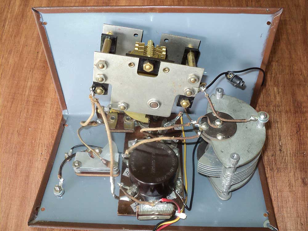
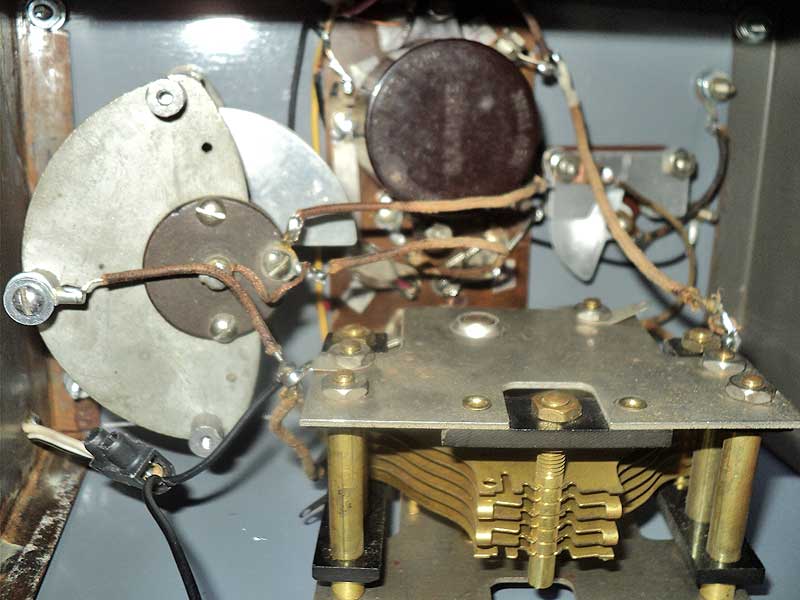
The apparatus was badly rusted and its paint very deteriorated as can be seen from the pictures shown below. Its electrical circuit was made from flat copper strips joined together by means of rivets most of them making false contacts .Due to this , every joint was re-soldered and a ground bus wire interconnected all ground points to prevent any future problems. This precaution really pay off because, now the Dresner can be enjoyed due to its excellent mechanical stability. Please click on images to enlarge.

|

|

|

|
A. Re-assembling the Dresner
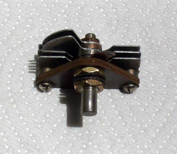
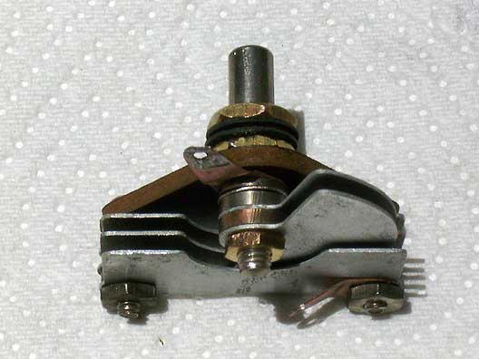
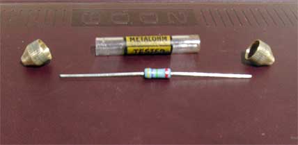
Before re-assembling the Dresner all of its parts were carefully tested, cleaned, and fixed, if it was needed. Fortunately the 150 pF grid leak "mica" condenser and the 1000 pF by pass "mica" condenser were both good. So they were just cleaned. The circuit board was specially cleaned and all the joints of the circuit were re-soldered.On the other hand the antenna coupling condenser was taken apart, carefully cleaned, and put together again; while the 5.5 MOhm was reconstructed using a 4.7 MOhm resistor, and encapsulated again in its original glass cylinder. These procedures can be seen in the pictures below. Please click on images to enlarge.

|
|
|

|

|

|

|

|
|

|
B. Painting the cabinet
The cabinet was sand-papered to a certain point only. Then it was painted as close as possible to the original brown color using an oil-based spray can paint. The pictures are self explanatory. Please click on images to enlarge.

|

|

|
C. Wiring the circuit
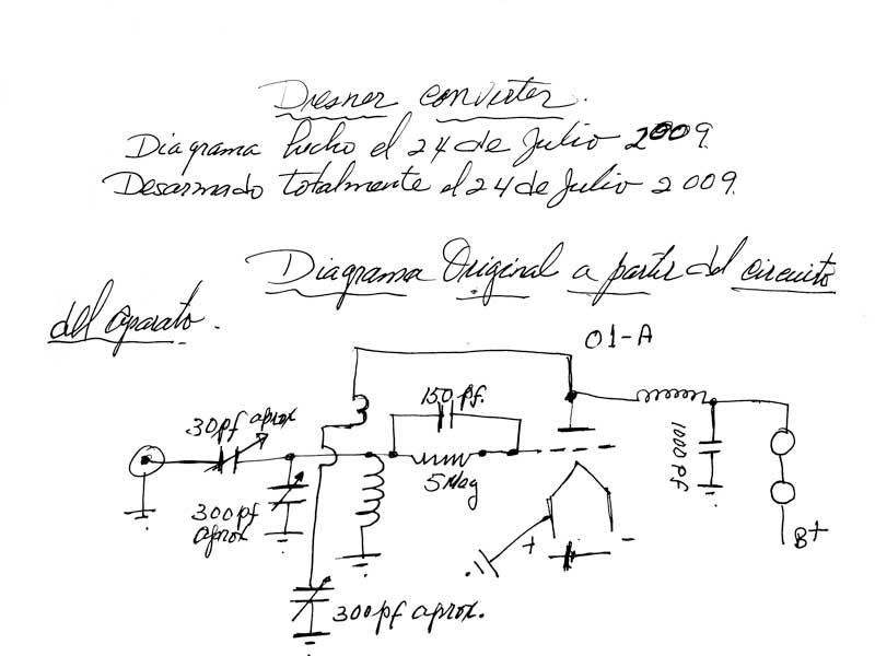
Before taking the Dresner apart the original circuit was traced, and put on paper. The earphone symbol was added only to indicate that the radio could be used with 2000 ohms earphone. The circuit is the one shown below. Please click on it to enlarge.
|

|

|

|

|

|

|
|

|

|

|
|
A large number of pictures were taken in order to show a step by step process, but unfortunately one mistake was made at an early stage of the wiring. So pictures containing this error were removed. Also during initial testing of the Dresner it was found that, a much better performance was obtained, if the stator plates of the antenna coupling condenser were connected to the grid leak resistor, and the moving plates to the antenna post. Only correct photos are shown. Please click on images to enlarge.
D. Coils construction
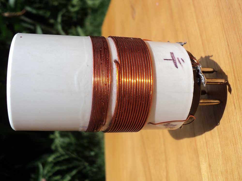
The coil is wound on a 1 inches (about 3.9 cm) outer diameter plastic tube, of length 2 inches (about 6.5 cm). This plastic tube is mounted on a 4 prong base removed from a discarded 4 prong tube. The tickler coil has 10 turns, close wound, of №25 enameled wire. The grid coil has 15 turns, close wound, of №20 enameled wire. Both windings go in the same direction and are separated 1/8 of an inch. To see the coil please click on images to enlarge.
|

|

|
Using this coil provides the following results:
- Dial reading: 0. Approximate frequency: 7.7 MHz. Condenser at minimum Capacitance;
- Dial reading: 50. Approximate frequency: 5.5 MHz. Condenser at mid Capacitance;
- Dial reading: 100. Approximate frequency: 3.7 MHz. Condenser at full Capacitance;
Power supply
For simplicity, and to avoid hum as much as possible, a battery power supply capable of producing 18 Volts and 5 Volts was chosen.The 18 Volts are provided by two 9 Volt batteries connected in series. While the 5 Volts are provided by four 1.5 Volt batteries and a 4 Ohm 1W resistance connected in series. This resistor is needed to drop the 6 Volts to 5 Volts, which is the operating voltage of the filament of the 01-A detector. The audio choke is provided by the primary of a small, but high resistance (1260 Ohms) audio transformer.
The total current drained by the plate of the 01-A is only 0.24 mA. Therefore the 9 Volt batteries are practically eternal. Not so the 1.5 Volt batteries that are subjected to a drain of 0.25 A. The diagram and some pictures are shown below. Please click on images to enlarge.

|
|
|

|

|
Operation of Dresner
Since the Dresner is a one tube regenerative detector it requires an audio amplifier or the use of a 2000 ohms earphone. I use this radio with an IT-12 Heath kit signal tracer. Any amplifier using a 12AX7 and a 6AQ5 will do more than fine. The following guide should prove useful:- Set the regeneration condenser at minimum capacitance.
- Set the antenna coupling condenser at about 1/4 of its trip.
- With the actual coil the 25 dial mark correspond to about 6MHz and many stations will be found here. So start tuning either side of the 25 dial mark.
- Mesh in the regeneration condenser to the point of oscillation, and then back off a bit.
Now you are ready to tune in stations and to have fun with this little receiver. To see the installation of the Dresner, please click on images to enlarge.

|
|

|
Final remarks
The Dresner (called a converter) is a device initially intended to be used with a tuned radio frequency (TRF) BC receiver. It uses the radio's detector tube, which is removed from the BC radio, and then it is plugged in the tube socket of the converter, from which a harness of wire, ending in a four prong socket, is plugged into the empty tube socket of the BC radio. This harness of wire carries the filament voltage to the converter. It also carries the audio from the converter, applying it to the primary of the first audio frequency transformer of the BC radio. This process converts the BC receiver into a Short Wave Receiver. This is why the Dresner is called a “converter”.In order to use the Dresner as a regenerative detector radio, independently from a BC receiver, I made a PS using batteries and provided the audio choke. To listen to it I used a Heath kit signal tracer IT-12.
Results are better than expected: the stability is very good, it's sensitivity is also very good and the selectivity, if the regeneration control is operated properly, is very acceptable.
Finally I want to thank my friend German for posting this article in his site and my friend Aaron Weed KC2NDA for bringing this radio from New York.
Add comment:
| Name: | ||
| code protection:* | ||
| email:* | ||
 Main
Main- About
- Antique radios
- Old Radio Collecting
-
Radio repair links
- Old Radios Troubleshooting Quick Guide
- Tube radios repair technology
- If you receive the parcel with an old radio
