738 Silver Marshall Shortwave Converter Restoration
738 SM Recovery
Author: Edgardo Castro Bruse
| Author: YS1ECB AUGUSTO EDGARDO CASTRO BRUSE Calle Loma Linda Residencial Loma Linda casa No. 4 Col. San Benito. San Salvador. El Salvador. |  |
San Salvador , July 22 , 2007
Motivation:
Some time, in the beginning of September 2006, I gave a friend of mine two EL86 tubes in exchange for a beautiful National type E dial. I did some research on the internet and found that the E dial was used in the SW-2. The idea of making a replica of the SW-2 began to attract me very profoundly.
 After two weeks of visiting my friend again, he said, "I have this box for you. This is the box that had the dial I gave you. " He then told me that he had found the "box" about 25 years ago at the home of Eng. Federico Mejia (YS1FM), who was his uncle, and that very likely it belonged to him.
 I had met YS1FM in the early 70's when I was very young. He was very well respected in the amateur radio community as well as in engineering circles for directing the installation of Radio Nacional de El Salvador in 1926!
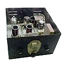
These new events gave momentum to the idea of determining what kind of apparatus the "box" was and to restore it to honor the memory of Eng. Federico Mejia (YS1FM). I continued my research on the web until I found a very minute picture of the 738 Silver Marshall. The picture gave me evidence beyond any doubt that indeed the "box" was the 738 Silver Marshall short wave converter.
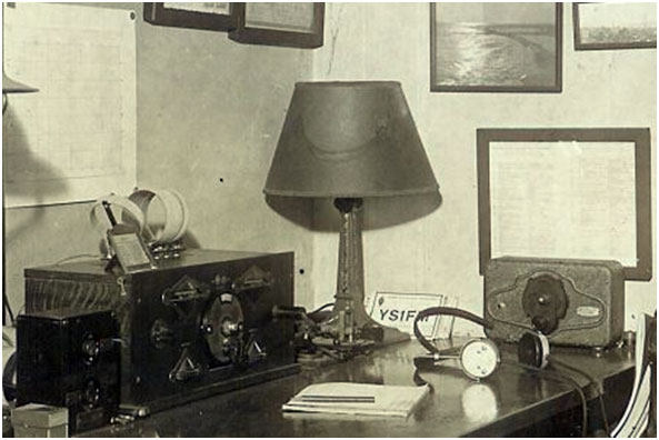
Shortly after that, I found a site that showed a picture of a 1930 station. To my amazement, this picture shows that the owner of such a station had received a QSL from YS1FM!
Restoration Process
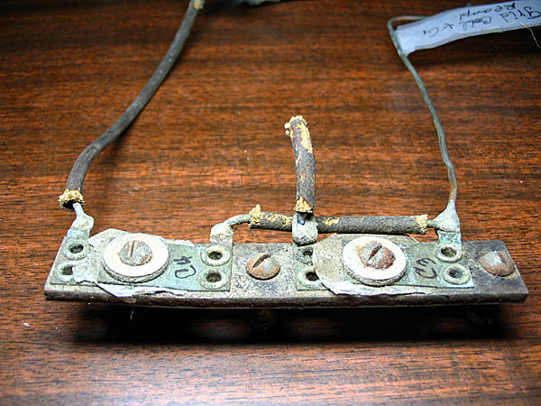
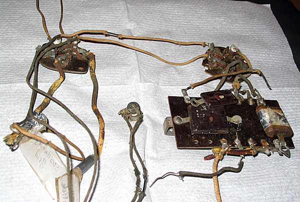
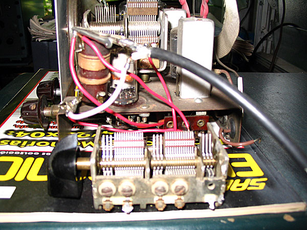
The old unit had been outdoors for about 25 years and I was told that the "box" had been used by hens to lay eggs. The pictures shown here give testimony of the deplorable situation of the 738 Silver Marshall.

The box was thoroughly sand papered and painted with a computer prepared dull black. The paint was sprayed using a professional painting pistol. No base was applied before the application of the paint. The reason for this was that the "box" was severely rusted and after sand papering it, it's surface became full of pores. Spraying the "box" in this condition resulted in a finish showing something like natural aging, and simultaneously neat.

The vernier and the factory plate were intact, because they had been kept in a closet for years.

Parts Obtaining
This process required the cooperation of several friends. Since the diagram did not indicate, the B+ nor did it give the secondary's High Voltage, I decided that 180 volts AC would work. The filament voltages were 1,5V at 1,5A and 2,5V at 4A. My friend, Jose Argueta, volunteered to wind the transformer for a nominal fee of $10. The transformer looked and worked just as a factory made one.The Silver Marshall 738 requires one type 26, one type 27 and one type 24-A. I was missing the 24-A and my friend NN5E, Paul Kelly, kindly donated me the tube and it's shipping to El Salvador.
The rest of the parts, condensers, resistors, tube sockets and coil forms were found in the junk box or bought locally.
Technical Information:
One of the goals was to restore the Silver Marshall 738 as close as possible to the one manufactured by Silver Marshall. (Please note the Silver Marshall 738 was also sold in kit form.) To accomplish this, actual photos were needed. I wrote to a number of friends and searched the web almost every day.
My friend W8UT, Al Parker, put my request for pictures on a list on the web, and KB2EVN, Ludwell Sibley, sent me an original diagram of the Silver Marshall 738. But I had not obtained pictures yet. One day while checking E-Bay, I was astonished to see that a seller JRC Radio (Jim) was offering a Silver Marshall 738 for sale and had posted several great pictures of it. At my request, Jim, very kindly, took additional pictures that were very useful in the reconstruction of the Silver Marshall 738. Meanwhile, NN5E (Paul), after several weeks of a stressing business relationship with Radio Era Archives, was able to buy the original manual of the Silver Marshall 738 and get it sent to El Salvador.
Finally Paul got me in contact with K8JRM (Tom Laszinski), who also owned a Silver Marshall 738! Tom sent me a total of 26 additional pictures! Last but not least, my friend David from NSVRS (New Zealand Radio Sociaty) sent me an article on the Silver Marshall 738 written by John Stokes. I very much enjoyed reading this article. This article provided me with the capacitance value of the two variable condensers used in this unit.
From a situation of zero information, I now had the manual, the original diagram, Mr. Stokes' article, a few ads, and dozens of useful pictures. Most important, I had a team of friends that made possible the restoration of probably the only Silver Marshall 738 short wave converter in the entire Central American area.
At the same time, Ing, Federico Mejia (YS1FM), a radio pioneer of El Salvador, has been honored by the restoration of his Silver Marshall 738.
Many thanks to the Silver Marshall 738 team!
The dual filter condenser C8 restoring
This is an 8uf + 8uf paper condenser enclosed in a tin can. The tin can was opened using an acetylene torch to carefully melt the solder. With long nose pliers, the can was partially opened, and the condenser was pulled out of it.Immediately the can was placed under an open faucet, cooling it with running water. At this point, paint solvent was applied to remove the asphalt like substance inside the can.
The next step was to carefully sand paper the can, and to open it sufficiently to permit the installation of the new and modern electrolytic condensers.
For the input of the filter system a 10mkf/350v condenser was used (Red Wire) and for the output a 30mkf/350v condenser was used (Blue Wire). To finish the job, the tin can was closed, soldered with a 100 watt soldering iron, and painted.

Restoring the choke
The PS choke SM338U, was completely rusted and lacked one lead.After removing the first layer of insulating paper, the beginning of the winding was found.
The DC resistance measured 2314 ohms, which compared very well with the rated value of 2400 ohms for the SM338U choke. In view of this its terminals were repaired and the choke repainted.

Now the filter, choke and filter condenser were ready.
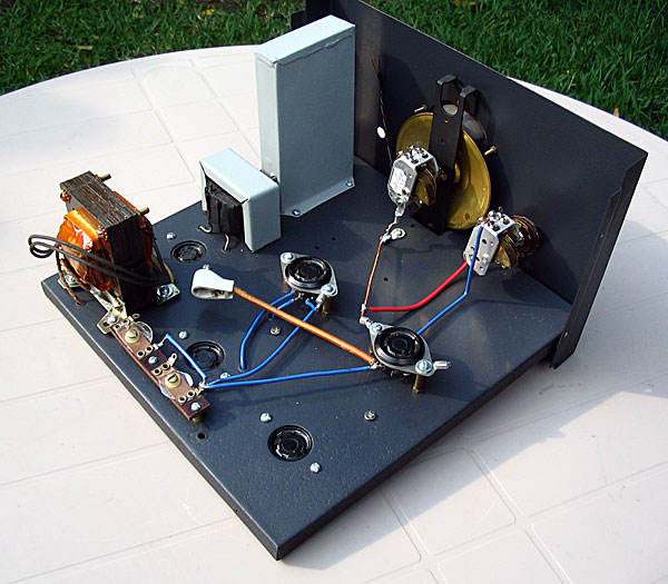
Assembling the SM738
I started by mounting parts on the chassis with the parts I had at that moment (namely: power transformer, filter choke, dual filter condenser, the tube sockets, coil sockets, and the C3 C4 dual trimmer condenser strip). Note: C3 C4 had been previously cleaned with paint solvent and pure lime juice. Finally C3 and C4 were washed with running water and dried with a hair dryer.
After all parts were on the chassis, the filaments and power supply wiring was done. A provisional 2000 ohm resister was included in series with the plate of the 26 type rectifier.
Also a permanent 0,1 ohm resistor was installed in series with the 2,5V winding and the 2,5V filaments to provide the rated 2,5V to these tubes.


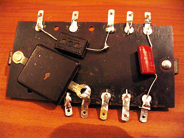
Restoring the circuit board
All components except C6 were removed from the circuit board.Every lug of it was carefully cleaned and tinned.
After the circuit board was shining again, I carefully measured all components and found that the four resistors were off by more than 100% their original values. R1 and R2, the 300000 ohm resistors, were replaced, each, by two 150k in series. To my surprice C6, the oscillator's plate by-pass condenser, still had its nominal value of 0. 005 mkf, and presented absolutely no leakage when tested with 200 V across its terminals. A zero to 50 microampers meter was used to look for leakage. So C6, the big squared shaped condenser with a red dot on it, was conserved. The other two condensers were replaced. See images below for the process:


The 738 has two 5 pin bases and one 4 pin base. The 3 bases were cleaned and are usables, but I broke one support ear of one of the 5 pin basses, so to keep simetry I replaced them all with amphenol bases.
Wiring the under chassis
This wiring consisted in connecting the circuit board to the lugs of the tube bases. To do this the 738's diagram was used along with the pictures I made when I disassembled the unit.Also the pictures sent by JRC radio, Jim, and Tom Laszynski were the vivid references to do the wiring as original as it could possibly be.

Mounting the Vernier and front plate
This process is self explanatory: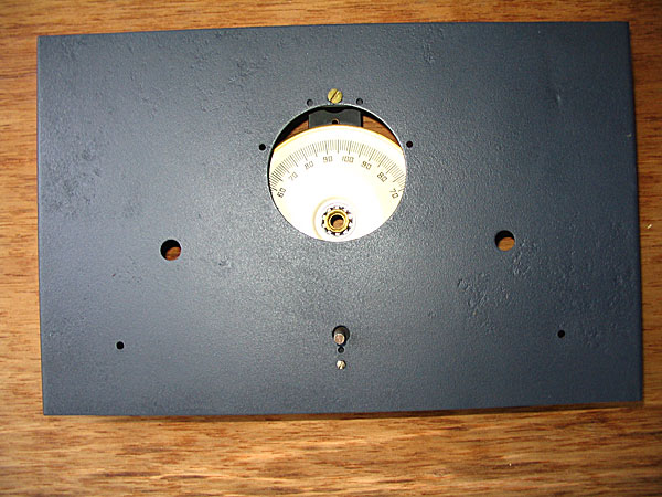


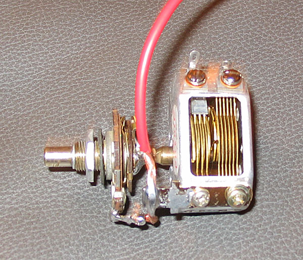
Preparation and mounting of C1
C1 is a 150 pf, single hole mounting, variable condenser.To adapt the 160 pf condenser that I had, to a single hole mounting style, I took apart a volume control and discarded its back cover. Then I centered the small shaft of my condenser with the center of the axis of rotation of the volume control's sliding arm, and solder them. The operation was a success, but when the shaft is turned it woobles a little bit. To compensate this, the ground connection of this condenser is made with very flexible wire. This is the only wire that, strictly speaking, is not in the same location as the original wire was.
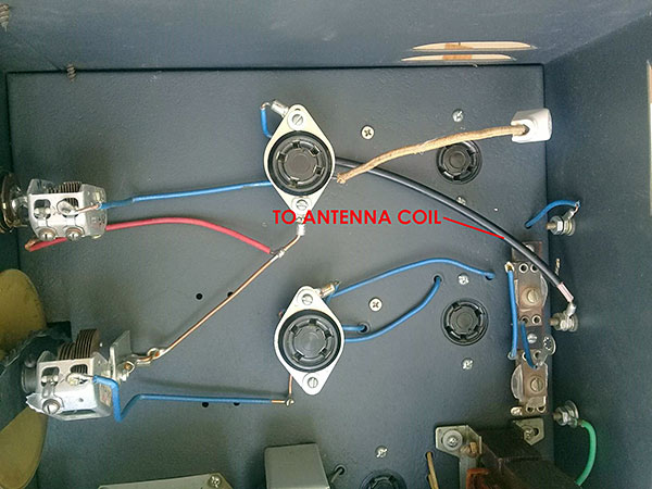
Wiring the top of the chassis
This wiring consisted in connecting the oscillators's condencer C2 to the oscillator's plug-in coil socket lugs and to the oscillator's socket lugs.Also the mixer's condenser C1 is connected to the mixer's plug-in coil socket lug and to the mixer's grid lug. Finally the antenna and the oscillator injection trimers are connected Ref Photos 718 and 719 along with Set 1, Set 2, and Set 3 were all used in the effort to make the wiring as close to the original as possble.


Finally the original AC switch was completely taken apart, cleaned, lubricated and installed again. This completes the entire wiring of the SM 738. Unfortunatelly I took no pictures of the restoration of the AC switch.
Construction of coils
I decided that I wanted to cover two ranges: 1) 4,8 MHz...7,8 MHz and 2) 9 MHz...18 MHz.This decision pretty much covered my desire to copy WWV at 5 MHz, 10 MHz, and 15 MHz, and to include the most active short wave bands in order to enjoy SWListening. After consulting several articles on short wave coils and doing some trial an error I built the first set of coils to cover from about 9 MHz To about 18 MHz. I made the grid coil of the 227 oscillator identical to the antenna coil of the 224-A mixer. I hoped that the tickler's capacitance would reduce the oscillator's frequency to the point that I could produce a 1 MHz IF. The finished coils and the two vacuum tubes were inserted in their sockets. With a Millen 90651-A GDM I verified that the antenna coil would resonate from about 8,6 MHz to about 20,6 MHz, and that the oscillator's coil would resonate from about 8,75 MHz To about 19,9 MHz As we can see it is easy to keep an IF of 1 MHz. Keep in mind that C1 and C2 are 160 pf each.
Coil's Data:
ANTENNA COIL: 6,5 TURNS No 22 Enammeled wire spaced over 1,7 cmOSCILLATOR'S COIL: Identical to Antenna Coil
OSCILLATOR'S TICKLER COIL: 5,5 TURNS No. 26 Enammeled wire, closewound separated 1/8 of an inche from the grid coil and wound in the same direction.
The antenna coil and the oscillator coil are wound over T-49 D Tanaka coil forms. These are 5 prong forms with an outer diameter of about 31 mm equivalent to about 1¼ inches.

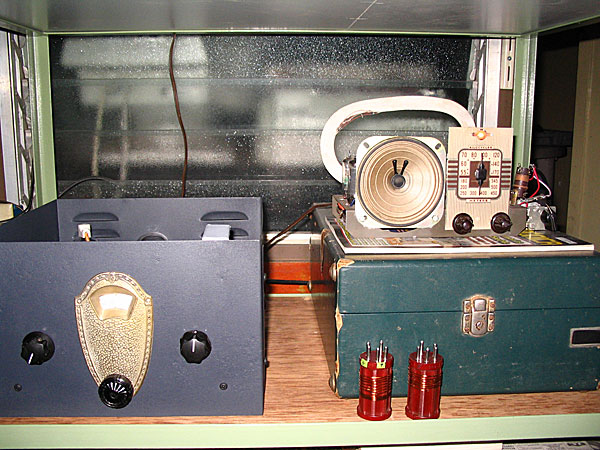
Testing the 738 SM
I hooked-up the 738 to my HQ 129X tuned to about 1 MHz Inmediately, as I rotated the 738 vernier, stations began to pour-in, and I was simply astonished! The 738 SM was working again, after probably, a recess of about 75 years! For the next few days I was so happy that I did not stop to look for drawbacks. I just enjoyed it. The HQ-129 X is a gigantic receiver and, of course, an extremely efficient IF amplifier so I wanted to try the 738 SM in a small BC band only receiver. I selected a little 5 tube AC-DC type receiver and attached the 738 SM to it by means of a coupler. The result was EXCELLENT SENSITIVITY, good selectivity along with a few problems.
The most relevant problem found was that the antenna tunning-in some small band segments-pulled the oscillator out of frequency, tunning in a station that was not expected to be tunned there. I corrected this problem, to some degree, by reducing the injection trimmer C4 to 7 pf. I had pre-calibrated C4 and C3 to 15 pf each one.
To minimize this problem the most, a partition separating the oscillator coil from the antenna coil is needed. I did not put it to keep the 738 close to the original, and by this time I had become an expert in using the 738. Other problems included a couple of dead spots, and a feed back noise at a few points where the antenna coil seems to resonate with the oscillator coil, When I constructed the lower frequency coils I learned that all three problems can be significatly reduced by simply making a tickler coil with more turns and tighter coupling in order to obtain strong and stable oscillations. This became particularly true for the high frequency coils. I have made a test interwinding the turns of the tickler coil with the the turns of the oscillator's grid coil with greatly improved results. When I get the optimun performance I will post the information. Therefore I will post only the information for the 4,8 MHz to 7,8 MHz coils.
Data for 4,8 MHz to 7,8 MHz coils C1 = C2 = 160 pf.
ANTENNA COIL: 15 3/4 TURNS No 22 Enammeled wire spaced over 1,8 cm
OSCILLATOR'S COIL: Identical to Antenna Coil
OSCILLATOR'S TICKLER COIL: 10,5 TURNS No. 26 Enammeled wire, closewound separated 1/8 of an inch from the grid coil and wound in the same direction. The antenna coil and the oscillator coil are wound over T-49 D Tanaka coil forms. These are 5 prong forms with an outer diameter of about 31mm equivalent to about 1 1/4 inches.

This set of coils turned out better than expected.
If the oscillator is tunned 1 MHz below the incomming signal, the 738 will tune from about 5,275 MHz to 10,8 MHz, and if the oscillator is tunned 1 MHz above the incomming signal it will tune from about 4,350 MHz to 8,980 MHz I have been using this set of coils for several month, and I am convinced that this set is very near to optimun performance. Therefore these coils should work well in any 738 Silver Marshall Converter. Final data for the high frequency coils will be posted when more experimenting yields the best possible performance.
ADDENDUM to the Silver Marshall 738
I have several short wave converters, and the Kennedy 53 has always amazed me, because of its good sensitivity and simplicity. It does not have an antenna tuned circuit! This converter operates its 24-A mixer with full plate voltage through an RF choke, and moderate screen voltage (60 volts) through a voltage divider.
The SM 738 also operates the 24-A mixer as a tetrode but with very large resistances (300,000 ohms each) in the plate and screen circuits. I decided to experiment and operate the 24-A in the SM738 the same way it is operated in the Kennedy 53. The changes are shown in a diagram and compared to the original one.

The oscillator´s signal was now injected to the cathode by means of a condenser. Please see diagram. The results were amazingly good. Please see pictures of the modified SM738.
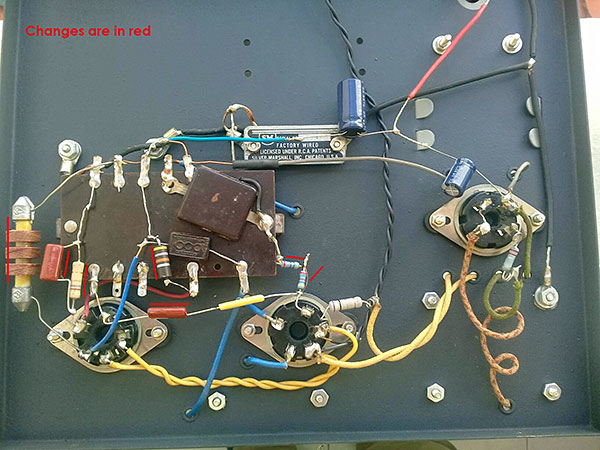
This work encouraged me to work on the coils too. I modified the antenna transformers I already had and ended up with Set A and Set B which are described in the photographs below.

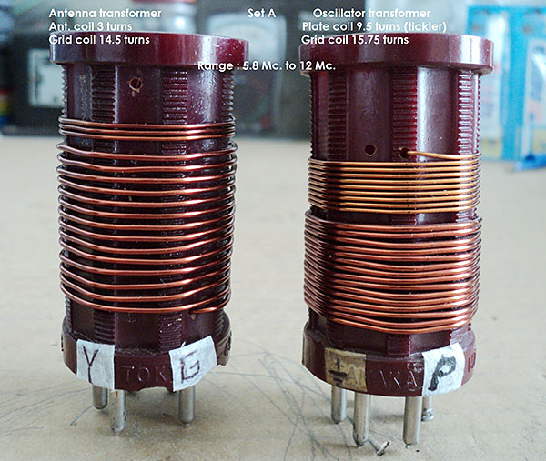
Conclusions: Now the SM 738 operates more efficiently in two ranges Range A from 5,8 MHz to 12 MHz and from 10 MHz to 15,8 MHz.
Add comment:
| Name: | ||
| code protection:* | ||
| email:* | ||
 Main
Main- About
- Antique radios
- Old Radio Collecting
-
Radio repair links
- Old Radios Troubleshooting Quick Guide
- Tube radios repair technology
- If you receive the parcel with an old radio
