Restoration methods
Antique capacitors types
Paper/Wax
These are usually 1/4" to 3/4" wide wax covered cardboard cylinders with leads coming out of wax plugs at each end. Occasionally, they can also be found as rectangular metal "bathtub" cans with values stamped on them, but no polarity markings. Paper caps are the most abundantly used type, found in all areas of the radio circuit for general coupling, decoupling, and filtering. They are non-polarity sensitive, with values typically ranging from .001uF to .47uF. Most of these capacitors are clearly labeled with both value and voltage rating, with the actual measured value being quite close. They often have a black band around one end, indicating which lead is connected to the "outside foil" of the capacitor. This end should be connected to the more quiet or less sensitive side of the circuit, so the outer foil acts as a shield to reduce cross-talk with the other components. This is less of a concern if new capacitors are installed, as they have smaller size, better construction and will not be as likely to couple.
Paper caps tend to be fragile in nature, and are even more so when they are old or partially melted from the heat under the chassis. Damage to these caps is usually indicated by melting, bubbling or darkening of the outer wax covering, loss of wax from inside or one end, or as loose leads. The caps that are connected to the high voltage parts of the circuit are the most likely to fail. These caps will more often become an open rather than a short when they fail. They can be tricky though - sometimes they can look and test OK, but have electrical leakage when at working voltage that makes them act more like a resistor. This is a big problem if the cap is used as an audio input coupling cap for the input grid of the audio amplifier tube. Leakage here can cause DC bias current through the tube to increase enough to burn out either the audio tube, output transformer, or even the power transformer. In general, replacing paper caps with more robust modern types will greatly improve the long-term reliability of your set.
The nature of the paper/foil construction leads to a large physical size for high working voltages or values. This large foil plate area and lead length contributes to the parasitic inductance and series resistance of these caps, which is relatively large compared to modern ceramics or "orange drops". These parasitic qualities limit the effectiveness of these caps at very high frequencies. For this reason, replacing these caps with similar values of ceramic or orange drop types should reduce the overall amount of stray coupling, improve the high frequency response in coupling/decoupling, and improve the overall performance of the set in general. A nice added bonus!
Electrolytics
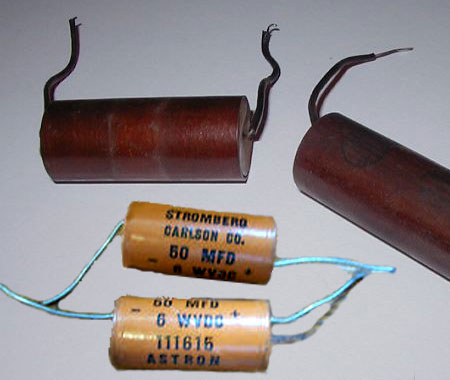 These are most commonly either a large aluminum cylinder mounted to the top of the chassis, or a large cardboard cylinder under the chassis with several colored leads. Both of these types usually contain several independent sections, joined to a common ground at the cylinder case or lead. Each section may have a different capacity value and working voltage. These caps are almost always used for power supply filtering. Common values range from one to several hundred uF. The value, polarity, and rated working voltage should be clearly labeled on the side of the cylinder.
Electrolytics are used because they offer the greatest capacity per volume, but are the most prone to failure. These caps are polarity sensitive, and can quickly short or blow up if the voltage or lead polarity is reversed. They will also fail quickly if the working voltage rating of the cap is exceeded. These caps are notorious for leaking out their fluid contents, or drying out and opening over time. They are most often responsible for loudly buzzing or humming sets, and damaged rectifiers and power transformers. Some indications of a damaged electrolytic include bulging of sides, white or tan deposits around the terminals or end seals, leaking of liquid contents, or having completely exploded, leaving sticky wads of foil and paper everywhere! Unfortunately, badly shorted electrolytics more often than not look completely normal. Electrolytics more than a decade old should be carefully tested for both value and leakage current. When in doubt about the age or reliability, change it out. It will give you piece of mind, and your children will thank you for the extra years of trouble-free performance.
Mica
These caps can be flat plastic stamp sized square blocks, or small black "pez" sized pills, or even small plastic cylinders. They are usually found in the high frequency tuning and detecting stages of the circuit. Values typically range from the 10's to 100's of MMF (means picofarad or pF). The value will either be stamped on the case as a single number representing it's value in pF, or encoded as a series of colored dots. There are some excellent on-line sources of information for deciphering the color codes of mica capacitors, such as the one at TIPS, HINTS & KINKS. Color codes can also be found in a variety of books such as the ARRL's Radio Amateur's Handbook. The color dot system is similar to the resistor color codes, and there are often several extra dots indicating type, tolerance, and characteristic of the capacitor. These caps perform as well as modern ceramics in high frequency applications, are very stable and durable, and rarely need replaced unless damaged. It is best to avoid replacing these caps unless absolutely necessary, as they affect the alignment of the tuned circuits in the receiver. A set will almost certainly need an alignment after some of these are replaced. Usual signs of damage are cracking of the plastic package, or melted spots from clumsy soldering jobs.Ceramic Disk
These capacitors began to appear in sets in the 50's, and are a more modern style. They are usually small tan, green or red discs ranging in size from shirt button up to a quarter. The values range from a few pF up to .1uF, with voltage ratings from 16V to over 1000V. The value may be clearly labeled, but is usually encoded using the numeric system described below. The voltage rating is usually omitted in favor of a thermal coefficient identifier. Versions of this cap with a 1000V rating are easily available, much smaller than paper caps, incredibly durable, have very little parasitic inductance, and work very well at high frequencies. They are an excellent replacement cap for most paper and mica types, but keep in mind that the working voltage must be verified before using them. Small working voltages are most common in many stores and junk drawers, so it is best to buy those that are specifically rated high enough. When in doubt, assume the rating is too low.Trimmer
 These small valued adjustable capacitors are often square white ceramic blocks with two overlapping metal plates separated by a thin shim of mica. They are adjusted by turning the screw head that compresses the plates together. They are also used in the high frequency receiving and antenna circuits. They can be found mounted to the chassis, or built into variable tuning capacitors, or the top of IF transformers. Values can range from 2 to 100 pF, and are used for fine adjusting or "aligning" the resonant frequency or impedance of a tuned circuit. Trimmers rarely fail, except through corrosion or cracking of the ceramic body. It is best to avoid adjusting these trimmer caps until you have the proper test equipment to verify the effects of what you are doing. Without a clear schematic or alignment chart, it is difficult to determine what function each one has.
Air Variable Tuning Condenser
 This main tuning cap is composed of a set of large rounded aluminum fins that mesh together when tuning the radio. As each fin is separated by a small air gap, they are referred to as "air dielectric". They are usually variable from a few pf up to 365-500 pF, with two or more independent sections and padder trimmers in parallel with the main fins. The trimmers set the minimum value of the main capacitors, and are set so that the sections "track" together. The sections adjust the resonant frequencies of either the RF amplifier stages, or the RF preselector and oscillator circuit to receive the desired radio station. These caps only fail if they become bent, corroded or worn out. Clean them with a small stiff paintbrush and alcohol, or an electronics spray cleaner. Replace the rubber grommets that insulate the capacitor from the chassis if they are crumbling. Clean and tighten the mounting screws, and clean the connections of any corrosion. Poor connections here will lead to no signal or flaky reception. Put a drop or two of light sewing machine oil on the shaft bearings at the front of the capacitor, and a little at the rear of the shaft too to keep it moving freely.
Add comment:
| Name: | ||
| code protection:* | ||
| email:* | ||
 Main
Main- About
- Antique radios
- Old Radio Collecting
-
Radio repair links
- Old Radios Troubleshooting Quick Guide
- Tube radios repair technology
- If you receive the parcel with an old radio
