Restoration of the Breting 40 Receiver
Breting 40 Receiver Restoration
Author: Edgardo Castro Bruse
| Author: YS1ECB AUGUSTO EDGARDO CASTRO BRUSE Calle Loma Linda Residencial Loma Linda casa No. 4 Col. San Benito. San Salvador. El Salvador. |  |
San Salvador , January 17, 2014
Introduction
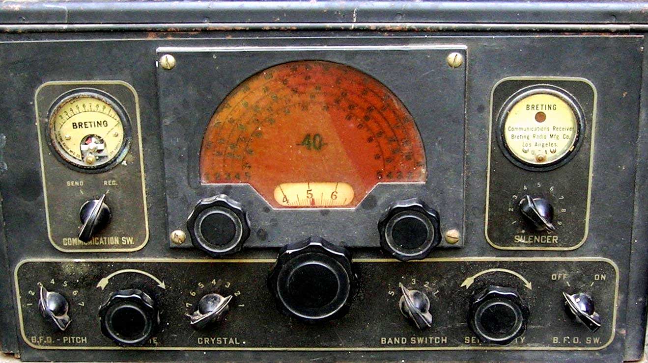 This interesting receiver was bought by a friend of mine, and while tracing its where about, it turned out to belong to a ham radio pioneer Eng. Miguel Angel Sol, YS1MS. In view of this I put a lot of time, effort and work to repair this radio to honor YS1MS and to provide my friend Mr. Salvador Galdamez, and the radio enthusiasts with information on a restored and working Breting 40 receiver.
This is a unique radio in several aspects. Since not very many were produced in the Breting Factory, at Los Angeles, California. I think it may be the only one in El Salvador and perhaps in Central America.

|

|

|

|
Radio before Restoration
The chassis was carefully cleaned by the owner who took a few pictures. Later I took many more pictures in order to help the viewer identify the complete wiring, and some particular areas that are of interest to any one attempting to repair the Breting 40 receiver. Please click on images to enlarge.

|

|

|

|

|

|

|

|

|

|
Radio after Restoration
All paper condensers were measured for leakage, and all but one had a leakage greater than 80 microamperes, therefore all were replaced. All mica condensers were left in place and all resistors that had a change in value greater than about 35% were replaced. The original wiring of the Breting 40 is unique in that, all leads are only inserted at the connection point, and not bent and tighten as in any other brand of radio. This makes the replacement of any resistance or condenser a lot easier. To see the new wiring, please click on images to enlarge.

|

|

|

|

|

|

|

|

|

|
Receiver's Circuit Diagram & Alignment Procedure
Description of the CircuitThe circuit diagram for the Breting 40 receiver is practically non-existing. Therefore a partial circuit had to be reconstructed by combining information obtained directly from the chassis, with the available information for the Breting 9, 12, and 14 models. I concluded that about 85% or more of the Breting 40 ia a combination of models 9 and 12. Models 9 and 40 have a very curious inter-stage audio amplifier that seems to provide and additional way to control the receiver's volume. This can be seen by observing the 6K7 driving the 6F6 in the model 9 diagram. A complete diagram of the audio amplifier was reconstructed. It is shown in the two handmade diagrams. Please click on images to enlarge.

|

|

|

|
The RF, MIXER, IF,BFO and DETECTOR circuits are basically the same as in the Breting 12 receiver. Except for the type of tubes. Diagrams of models 9 and 12 are also included for comparison and information. Note: I could not find out what was the use of the 6C5 in the Breting 40 receiver.
Alignment Procedure
The alignment was performed with an RCA RF generator the Viz-WR-50C, and a frequency meter from Optoelectronics.
IF Alignment
The intermediate frequency of this receiver is 432 KHz. As a first try I followed a standard procedure, and adjusted the IF transformers to Maximum S meter reading. This resulted in a too sharp selectivity and too much microphonism and a "hollow sounding radio".
 So, I made the following changes:
- The crystal filter was disabled by placing the Crystal Filter Control to its most counter clock position.
- I placed the RF generator hot lead next to the control grid wire of the 6J7 mixer. Use masking tape to keep both wires together. See fig 1.
- The left trimmer of each IF transformer was adjusted for Maximum S meter reading with the RF generator at 430 KHz. With a bit of 400 cycles modulation.
- The right trimmer of each IF transformer was adjusted for Maximum S meter reading with the RF generator at 434 KHz. With a bit of 400 cycles modulation.
Breting 40: Alignment & Conclusion
Oscillator AlignmentFirst locate the trimmers and padders by looking at Figs 2, 3, 5 and 4 respectively. Please clik on images to enlarge.

 |  |
Calibration Procedure for Oscillator
| Band | RF Generator | Dial's reading | Adjust... | |
|---|---|---|---|---|
| 1 | 1400 KHz. mod | 1400 KHz | Trimmer to 1400 KHz | |
| 600 KHz. mod | 600 KHz | Padder to 600 KHz | ||
| 2 | 3 MHz. mod | 3 MHz | Trimmer to 3 MHz | |
| 2 MHz | mod 2 MHz | Padder to 2 MHz | ||
| 3 | 6 MHz. mod | 6 MHz | Trimmer to 6 MHz | |
| 4 MHz. mod | 4 MHz | Padder to 4 MHz | ||
| 4 | 14 MHz. mod | 14 MHz | Trimmer to 14 MHz | |
| 8 MHz. mod | 8 MHz | Padder to 8 MHz | ||
| 5 | 28 MHz. mod | 28 MHz | Trimmer to 28 MHz | |
| NO PADDER ADJUSTMENT IN BAND 5 | ||||
Antenna and RF stage Alignment
First refer to Fig.4 to locate the appropriate trimmers. The strip of trimmers, closest to the front apron of the chassis, is the Antenna deck.
The next strip of trimmers is the RF deck.

Set the RF generator to the frequency shown in the chart for each band. Connect a piece of wire to the antenna terminal of the radio to act as an antenna. Place the RF generator about 2 meters away from the radio. Adjust its output to get an S-6 reading on the radio S meter.
Adjust the Antenna and RF stage trimmers for Maximum S meter reading.
Calibration Procedure for Antenna & RF Stages
| Band | RF Generator | Dial reading | Adjust... |
|---|---|---|---|
| 1 | 1400 KHz. mod | 1400 KHz | For Max. S meter reading |
| 2 | 3 MHz. mod | 3 MHz | For Max. S meter reading |
| 3 | 6 MHz. mod | 6 MHz | For Max. S meter reading |
| 4 | 14 MHz. mod | 14 MHz | For Max. S meter reading |
| 5 | 28 MHz. mod | 28 MHz | For Max. S meter reading |
Conclusion
The Breting 40 was a radio designed for ham operators and commercial companies that wanted to have point to point communication.
Some unique features
- You can use the radio's amplifier as a driver to a high power AM transmitter by selecting this function from a front panel switch.
- The entire wiring is designed to easy any future repairs. The leads of resistances and condensers are just joined and soldered, without bending and tightening them to connection lugs.
General features
- The IF transformers produced a very sharp selectivity, to the point that I had to calibrate their trimmers about 2 KHz above and below the 232 KHz. Crystal frequency.
- The sensitivity is very good except in band 5. Also, since there is no padder trimmer for this band, the dial calibration is not very good.
- The large toothed wheel produces a very pleasant and smooth tuning without back slash.
AKNOLEDGMENT
I would like to thank my friend, Mr. Salvador Galdamez for trusting me the repair of his unique receiver and for being extremely cooperative in the buying of the necessary parts to accomplish this job, as well as for being very supportive during the entire process.
Add comment:
| Name: | ||
| code protection:* | ||
| email:* | ||
 Main
Main- About
- Antique radios
- Old Radio Collecting
-
Radio repair links
- Old Radios Troubleshooting Quick Guide
- Tube radios repair technology
- If you receive the parcel with an old radio
