Stewart-Warner 301-A shortwave converter restoration
Cabinet restoration & mechanical repairs
Author: Edgardo Castro Bruse
| Author: YS1ECB AUGUSTO EDGARDO CASTRO BRUSE Calle Loma Linda Residencial Loma Linda casa No. 4 Col. San Benito. San Salvador. El Salvador. | 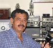 |
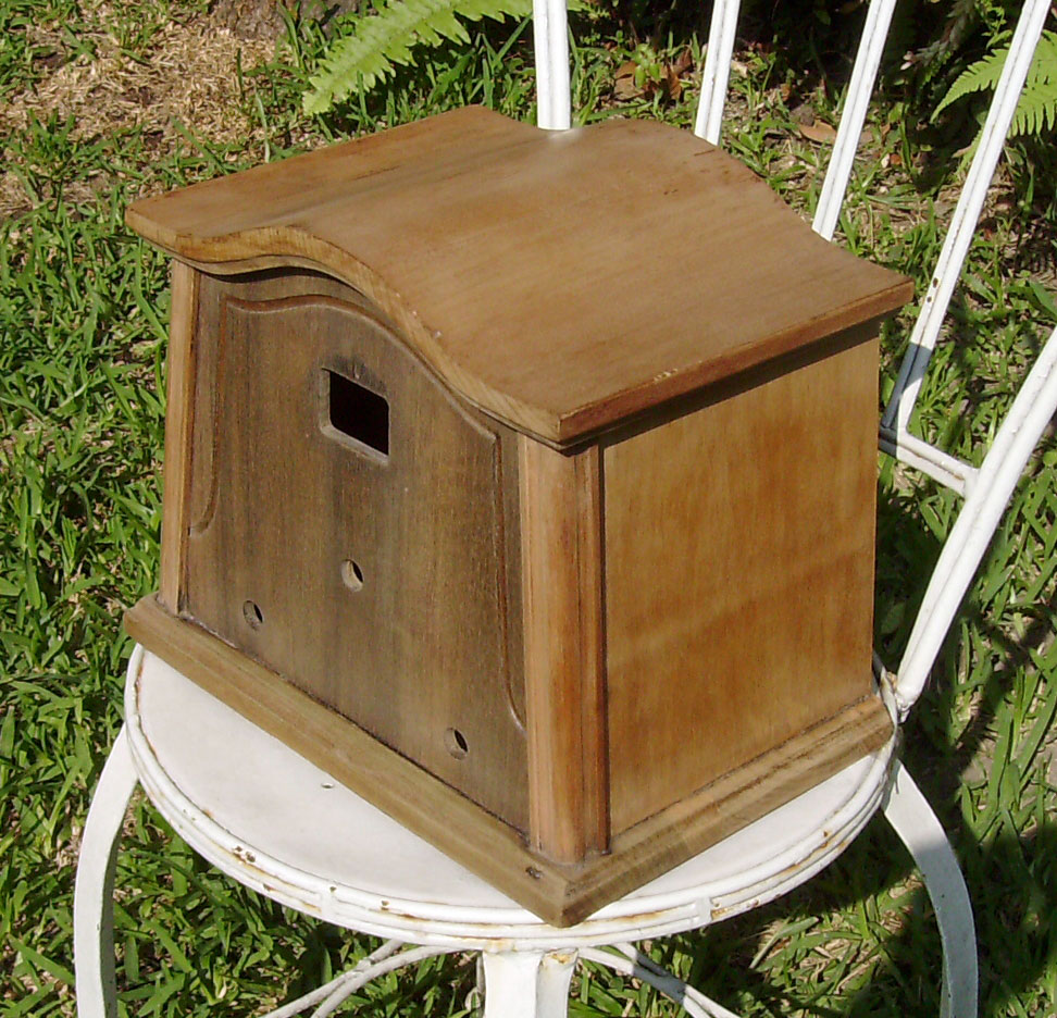
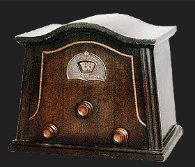
Having restored a 738 Silver Marshall Short Wave Converter from ground up, and after enjoying shortwave listening with it, I decided to venture into the world of the shortwave converters. Some time, in October of 2007, I bought a Stewart-Warner 301-A shortwave converter that looked like the perfect subject for restoration. The converter looked like shown in photos: (Click images to enlarge)
 |  |
Cabinet restoration
| Firstly, since the cabinet's bottom was falling apart, I removed it and re-glued it. Secondly I removed the old varnish by appling strips of Scotch Tape to the wood. Then by lifting these strips some varnish was removed easily. I removed the rest of it with sand paper. |

|
Finally I polished the cabinet with very fine sand paper and applied tint with a soft cloth. Process is shown below. (Click images to enlarge)
 |
 |
 |
 |
 |
 |
Mechanical repairs
The first problem was that the vernier system did not work, because the rubber cylinders that move the large toothed wheels were petrified and cracked.
To remedy this situation I disassembled completely the mechanism, and applied plenty of teflon tape to both rubber cylinders. Then when I tested the mechanism the large toothed wheels made the appropiate grooves on their respective teflon covered cylinder.
The repair is holding well untill now Jan 2010.
 |
 |
 |
Repair of electronic parts and circuit
Now, that the vernier was working, came the test.The converter's transformer provides only 2.5 V for the filaments of the 24-A and the 27.No B+ voltage is provided!! To provide the B+ I made a half wave power supply with a small transformer and a Pi filter. For this filter I used two 33Mf/160v capacitors with a 4.2 Kohms/1 W resistor in between both capacitors.
This provided a B+ of 92.2 volts and a plate voltage for the 27 type oscillator of 73.2 V. Just perfect! The location of the transformer and associated parts see below:(Click images to enlarge)
 |
 |
For this test, the converter was coupled to the Lincoln radio that is used with the 738 Silver Marshall Converter.
It worked with good sensitivity, but it showed a major problem: The band change toggle switches were making false contact, and the variable condenser was very noisy.
The variable condenser was fixed by removing both brushes, and cleaning them with an ink eraser rubber. Contact cleaner was aplied to the brushes and ball bearings. Finally a drop of thin oil was poured into the ball bearings at both ends of the shaft, and the body of the condenser was strapped to the chassis. See the photo above to the left.
The band change toggle switches are located to the left of the ANTENNA COIL.

An attempt to restore these switches was made. Both were completely taken apart throughly cleaned and oiled.

Unfortunately they worked well only a couple of month. Then, another solution was adopted.
Before addressing this problem, I must say that the 2 Megaohm grid leak bias resistor was found altered, and to bring it down to its correct value of 2 Megaohms, a 2.7 Megaohm resistor was connected in parallel with it.
The solution of the Band Change Problem was accomplished by strapping together three microswitches. To this bank of switches a foot was added in order to secure it to the chassis.


This photo shows that the Band Change Switch connects and disconnects three wires from ground. This is accomplished by a lever operating such a switch.

In my solution, this lever effect, is obtained by wrapping around the same shaft a green rubber lace, and tighting it well.
 |
|
Short wave converter operation
A small 5 tube AC-DC General Electric radio was chosen to operate with the 301-A converter.
To efficiently couple the about 100Kc. IF signal from the converter to the broadcast receiver, inductive coupling was used.
The inductive coupling was achieved by using a 4 Cm. long BC band ferrite antenna. The ferrite core of the antenna was removed, and the coil was slipped over the ferrite antenna of the broadcast receiver (the white General Electric radio).


The connection between the 301-A and the GE radio was accomplished by means of a 75 Cm. length of RG-58U coaxial cable, as seen in photo below:

The operation of the 301-A converter is simple.
First tune the BC receiver to about 100Kc. If this frequency is in use by a broadcast station find a quiet spot, a bit above or below the 100Kc. mark.
Second connect an antenna to the 301-A , and flip the Band Switch to its most clockwise position. This is the High Frequency Band, which tunes from about 4.9 Mc. to about 14.3Mc.
Search for stations moving the tuning knob from about the 27 mark to about the 40 mark. This will cover the range from about 6.0 Mc. to about 7.3 Mc.
A second very active spot is between the 50 mark to about the 64 mark. This range covers from about 8.9 Mc to about 10.4 Mc.
Finally there is a third active spot from the 75 mark to the 92 mark, which covers from about 11.6 Mc. to about 13.6 Mc.
Please note that you will also find stations in other positions. The spots mentioned above are simply most active from my location in El Salvador. Also take note that every division of the dial is two units of the logging scale.
The knob located to the right is the antenna compensator, and it should be moved slowly for maximun gain. In my converter a 9 o'clock position fits most ranges.
The second position of the Band Switch is the Medium Wave Band it goes from about 1.8 Mc to about 4.6 Mc. I will let you discover the most active spots here, but I recomend the 74 mark which correspond to about 3.35 Mc, and you can listen here Radio Exterior de Espaсa.
Final remarks
I use this converter with a single wire antenna, about 10 meter long and only about 1.5 meter above the roof.
I consider that its performance is very good given the antenna in use. I listen perfectly well to stations like: The Voice of Russia, Radio Croaccia, Radio Ucrania, Radio Vaticano, La Voz de los Andes, Radio Habana, NHK from Japan, Radio China Internacional, Radio Taiwan, The Voice of America, Family Radio, Radio Teheran, Radio Exterior de Espaсa, Radio Catуlica Mundial, etc.
I do think that the efficient inductive coupling used contributes a great deal to improve the overall sensitivity of the converter-BC radio system.
Finally I want to thank my friend German and my friend Aaron Weed KC2NDA for their time, patience, and skill in up-loading this article to their respective web sites.
Also I want to thank my friend Tom Laszynski K8JRM for his constructive conversation on the subject as well as for his pictures on the 301-A converter of his own. Tom's converter is housed in a different cabinet than mine. My 301-A's cabinet is the more common one.
Stewart-Warner 301-A circuit diagram

Plate supply plug (#67398) must be connected to some source of filtered D.C. at a potential of 180 to 280 volts. Recommended voltage is 250. The Ground Post of the converter is the negative return and must be connected to the negative side of the external plate supply. The table below gives plate voltages at both tubes for three different plate supply voltages.
| Plate Supply Voltage | '24 Plate | '27 Plate |
| 180 | 26 | 70 |
| 250 | 34 | 93 |
| 280 | 37 | 102 |
Notes on 301 A converter
 When connecting the Stewart Warner 301 A short wave converter to any receiver other than the 102-A, the following points must be borne in mind.
The plate supply plug must connect to a source of filtered DC inside the radio receiver that will deliver approximately 6 milliamperes at 180 to 280 volt, although the recommended plate voltage is 250 volts. If it drops below 180 volts the '27 oscillator tube may not oscillate at the higher frequencies. If it rises above 280 volts parasitic oscillations may be produced.
In this broadcast receivers in which the speaker field is in the positive side of the plate supply, a connection to the high voltage side of the speaker field will usually provide a satisfactory source of plata potential.
Where the speaker field and filter choke are In the negative side of the plate power supply, the correct positive potential for the short wave converter can frequently be taken off conveniently at the filament terminal of the 280 rectifier tube socket.
When tapping into the plate supply of any broadcast set, make certain that no resistors are being overloaded by the added drain of the converter. It is always safest to tap as close to the output of the filter as possible. Should this give excessively high voltage, it may be cut down to the correct value by means of a separate series resistor, capable of carrying 6 milliamperes safely. The value of this external resistor will be roughly 175 ohms for every volt in excess of 250. For example, if the B supply voltage is 350, a resistor of 17,500 ohms will be required to reduce it to 250 volts, which is the recommended value.
As a check on the correct voltage, the plate voltages at the tube sockets of the converter may be measured. The '27 tube plate should be kept about 90 volts when in normal operating condition. It should never drop below 70 volts or rise about 105 volts. The attached circuit data sheet gives plate voltage as measured with a high resistance voltmeter, of both tubes at input voltages of 180, 250 and 280.
The negative return of the Converter B supply is made thru its ground binding post to the broadcast receiver ground which, in a great majority of A.C. receivers, is at B negative potential. However, there are some sets on the market in which the negative 3 supply does not connect to the chassis . When the Model 301-A converter is to be used with sets of this type, the ground binding post of the converter must not be connected to ground but to the negative of the B supply system at a point inside the broadcast set. The broadcast set should be grounded in the usual way.
The plate supply lead of the converter should never go direct to a plate terminal of the broadcast set, since this may result in detuning and objectionable regeneration in the broadcast receiver.
The following advice should also be of interest:
- Don't tune above 33 meters for distant stations in daylight.
- Don't tune below 25 meters for distant stations after dark.
- Don't expect to hear many distant stations above 50 meters.
- Don't skim over the dials. Tune slowly.
- Don't expect to find stations on all parts of the dials. Short wave stations are widely separated except in a very few places.
- Don't expect stations to tune broadly. Most distant stations tune very sharply.
Stewart-Warner radios
The Stewart-Warner Company started in Chicago, where the firm erected a very large manufacturing plant on Diversely Street. Over time, the company expanded outwardly in all directions, including radio, which they manufactured from 1925 to 1956.
For the year 1940, Stewart-Warner was eleventh on a list of major radio manufacturers in the sales of radios. They were tied with Crosley with 350,000 radios sold. They also made radios for the major chain stores such as Sears and Montgomery Ward.
Add comment:
| Name: | ||
| code protection:* | ||
| email:* | ||
 Main
Main- About
- Antique radios
- Old Radio Collecting
-
Radio repair links
- Old Radios Troubleshooting Quick Guide
- Tube radios repair technology
- If you receive the parcel with an old radio
