Crosley 51 Regenerative Receiver
Crosley 51 Restoration
Author: Edgardo Castro Bruse
| Author: YS1ECB AUGUSTO EDGARDO CASTRO BRUSE Calle Loma Linda Residencial Loma Linda casa No. 4 Col. San Benito. San Salvador. El Salvador. |  |
Introduction:
Crosley is a Radio Company that always amazed me for its creativity, functionality and economy. Its "Book Condenser" and its series tuned antenna input circuit are unique. The regeneration control by means of flat front-back moving coil is simple and very effective.
Some time in November 2019 my son Edgardo bought for me a Crosley 51 and this is its story.

Restoration Process
The radio was in very good condition. It only had two connection points that had to be re-soldered, and its Filament Rheostat had to be cleaned and its resistance coil sandpapered.Also the grid leak resistance was replaced by Philips 3.3 Mega ohm resistance.


A LAMENTABLE MISTAKE
The radio came with its original Cunningham C-11 tubes which use 1.1 volts in their filaments. I thought they were Cunningham C-112 which uses 5 volts! Even thou I moved the filament control slowly I did not watch the color of their filaments and burn them!!! Due to this I had to use a CX 301-A for the detector and adapted a 1S4 as the audio output tube.


Cleaning the Rheostat
I measured the rheostat to be 30 ohms approximately.I used 3M metal sandpaper no. 500 to remove the oxidation layer on the wire resistance.
And 3-In-One Contact Cleaner to thoroughly clean it.
The disassembling and reassembling processes are shown in the pictures.
 |
 |
 |
 |
 |
 |
 |
 |
 |
 |
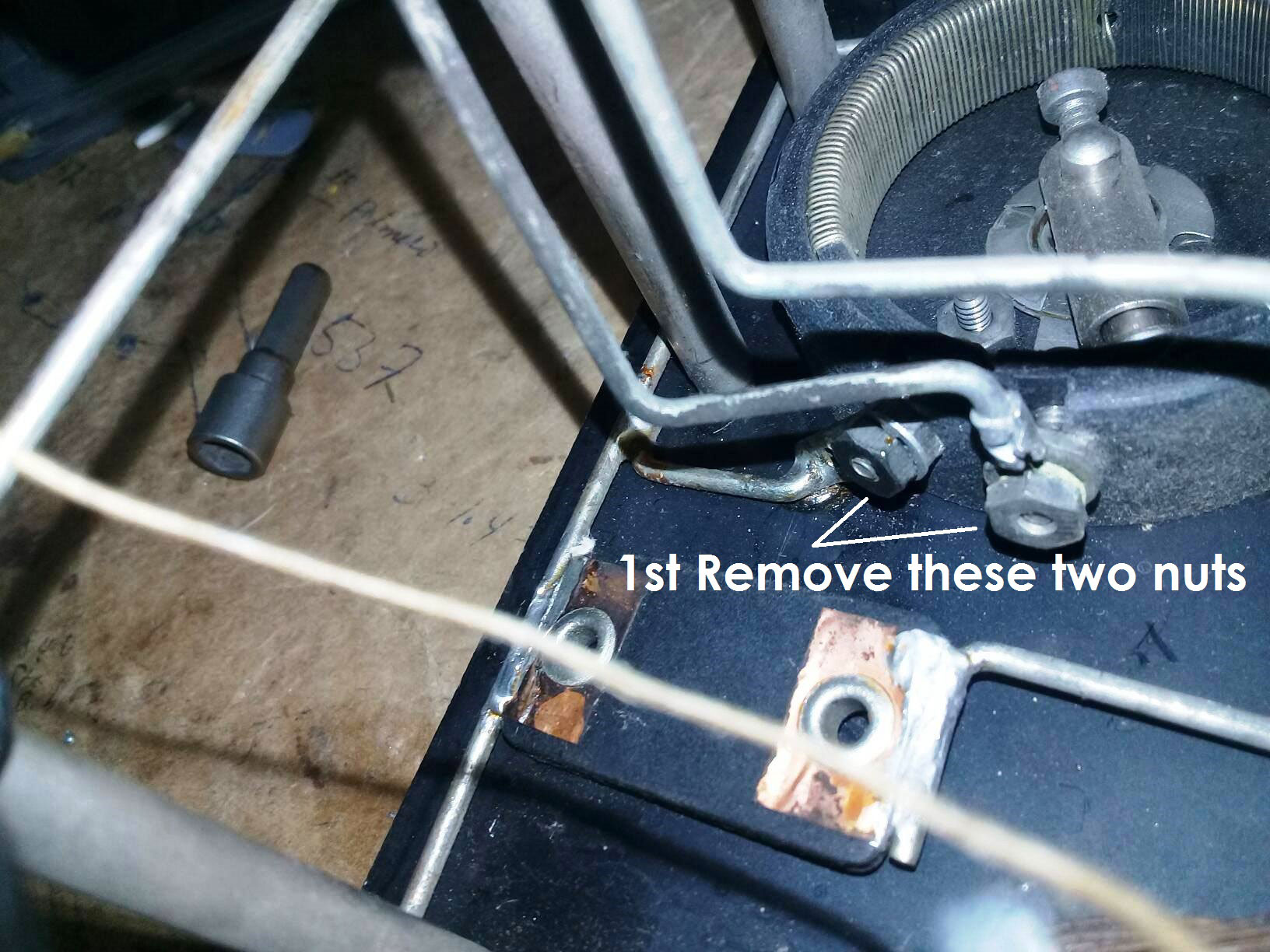
The Power Supply
All parts I used were found in my junk box.I used a 45 volt center taped transformer that was salvaged from and old audio unit.
I connected this transformer in a bridge rectifier configuration producing automatically 45 and 22.5 volts, under the light load presented by the Crosley 51. It is worth noting that the filter choke I used is the large resistance (322ohm) winding of a B & W TV Vertical Output Transformer. 45 volts are used in the audio stage and 22.5 volts for the detector stage.
For the filament supply I used a 5V/1 amp. Transformer connected to a bridge rectifier. I used a 2.5 ohm choke, salvaged from an old TV. Due to its relatively massive iron core (high inductance) and the use of two high capacity electrolytic capacitors (6800 mf/25 V) the hum produced is negligible.
See diagram and pictures:
 |
|
 |
 |
 |
 |
 |
 |
Operation of the Crosley 51
This is a Regenerative Receiver therefore all controls interact with each other. So tuning the radio properly is a "teach oneself process".Here are a few words that may help. The L/C ratio of the antenna tuned circuit can be varied by shortening the Antenna Coil by means of a rotary switch. The result of this is, that the SAME STATION can be tuned near the left position of the Condenser's Dial (near the 100 mark), or near its center position (around the 50 mark), or near its right most position (close to the 0 mark), all depending on the antenna coil tap being selected.
Note that INDUCTANCE increases as the rotary switch moves to the right. And the CAPACITY also increases when the condenser moves to the right too!
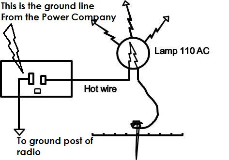
The regeneration control is smooth but interacts with the filament voltage. More filament voltage more sensitive it becomes. The Crosley 51 is a sensitive radio and a 5 or 6 meters long antenna, about 1½ meters above the roof will do perfectly well. It requires a good ground. If you do not have a ground near your radio I do suggest you used the earth line (grounded line) of the Power Company. Please see the picture to show how to to determine which is the the grounded line. This works amazingly well!
I am including the diagram made by Joe Sousa because the one found in Ryder's diagrams is not consistent with the real circuit.

Also I am including two PDF documents originals of the Crosley Co., that I found in internet.
Tube type WD-11 Instructions for Crosley 51
Crosley 51 Instruction Manual
Please see the Crosley 51, in its operating position and the output audio transformer salvaged from an old 1940s Murphy Radio. This transformer couples the audio very efficiently to 8 ohms modern earphones. It will drive nicely a 3 or 4 inches speaker specially if you increase the audio voltage from 45 to 90 volts.

ENJOY YOUR CROSLEY 51!
Acknowledgment: I want to thank my friend Raúl Urquilla YS1UF for continuing to encourage me to go along with the restoration and experimental projects. Also to my friend German for publishing this article.
Add comment:
| Name: | ||
| code protection:* | ||
| email:* | ||
 Main
Main- About
- Antique radios
- Old Radio Collecting
-
Radio repair links
- Old Radios Troubleshooting Quick Guide
- Tube radios repair technology
- If you receive the parcel with an old radio
