Crosley Trirdyn
Crosley Trirdyn Reflex-regenerative receiver
Author: Edgardo Castro Bruse| Author: EDGARDO CASTRO BRUSE |  |
Introductory Description
I bought the radio in December 2021 mainly because I wanted to experiment with a Reflex receiver.
The Crosley Trirdyn is a Reflex-regenerative receiver.
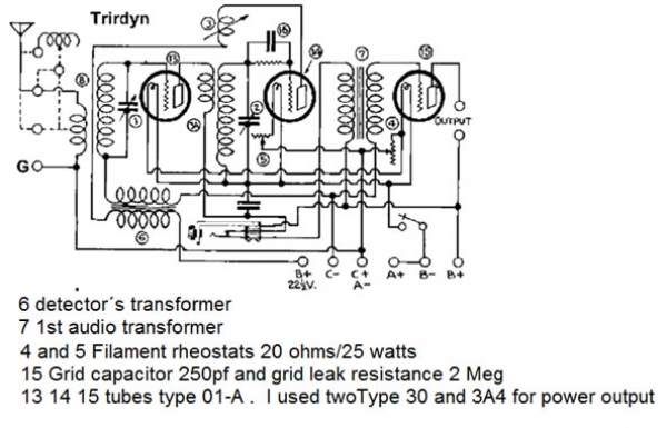
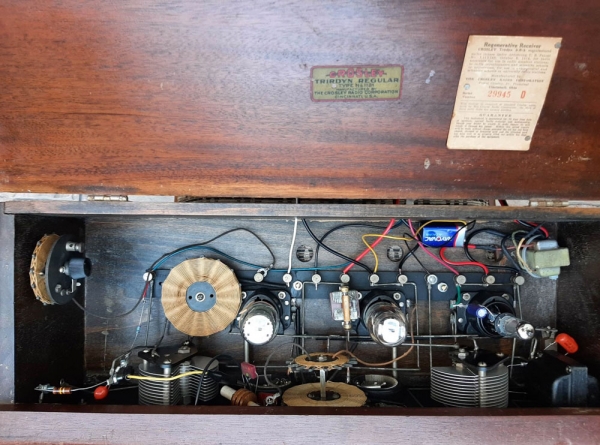
This radio uses three 01-A tubes. The first one is both, RF and 1st. Audio Amplifier. The second one is the regenerative detector, and the 3rd one - the audio output amplifier.
The regeneration is controlled by moving a tickler coil closer or farther away from the detector's coil.

The Reflex Action Path
The audio amplification begins at the tickler coil. This coil is in series with the primary of the detector's audio transformer, thus transferring the detected audio signal to it.
The secondary of this transformer is connected between the C- and the grid of the RF amplifier through the input tuned circuit. Now the audio signal and the RF signal are both injected to the grid of the RF amplifier and thus it becomes an audio amplifier too.
From the plate of this tube, the RF signal is transferred to the detector by means of the plate coil. The plate voltage of this tube is obtained from the primary of the first audio transformer which is connected between the B+ and the other end of this plate coil, and thus the audio frequencies circulate through the Primary of this transformer. It's secondary then drives the audio output tube. Please see diagram.
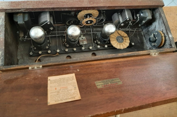
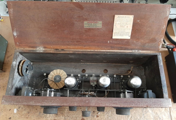
Crosley Trirdyn Before Restoration
The radio had the aspect of an abandoned radio.
The three 01-A tubes were bad and the spare one arrived smashed.
The rear reglette of the "chassis" was broken right at the middle.
The Detector's audio transformer had its secondary open, and the First Audio transformer had its primary open.
Also an inspection of all soldered joints was needed.
Therefore some hard work was in the horizon. Please see photos.



Cleaning of Rheostats
I had to re-solder a few broken connections and to glue the rear reglette of the "chassis", but the most extensive work was the complete cleaning of the rheostats. Please see photos.


Process to Make the Radio Work
As I pointed out before, the detector's audio transformer had its Secondary winding open. The first audio transformer had its Primary winding open. On top of this the three 01-A were bad. I wanted to have the best compromise between originality and functionality, so I experimented various ways to make it work. They can be summarized in: first attempt and final attempt.
First Attempt
I tried to use the good winding in each transformer using an LRC coupling in the detector and the first audio stages. This can best be illustrated with the diagram and pictures shown.


Results of first attempt
Results were: average performance, but I thought they could be improved.
Some problems were: the radio would run into oscillation very quickly at most frequencies. The tuning of the RF stage was very broad at some frequencies. The volume was moderate and a bit distorted.
Final Attempt
I made some important changes that resulted in a radio functionality with excellent sound.
- I put an RF filter at the output of the ticler coil. I used a PI filter made of a 2.5Mh choke and two 500pf mica capacitors connected at the input and output of the RF choke and ground.
- Instead of feeding the detector's plate through the primary of the detector's audio transformer;
I used a 200Kohms resistance for this function. This resistance together with the 0.022 capacitor and the 100Kohm resistance couple the audio signal from the detector to the grid of the RF stage that now, also amplifies the AF signal.
This makes this radio unique! - I put a semi-dead 9volt battery to provide a C- bias of -7,5volts. This by itself produced a quite notable improvement.
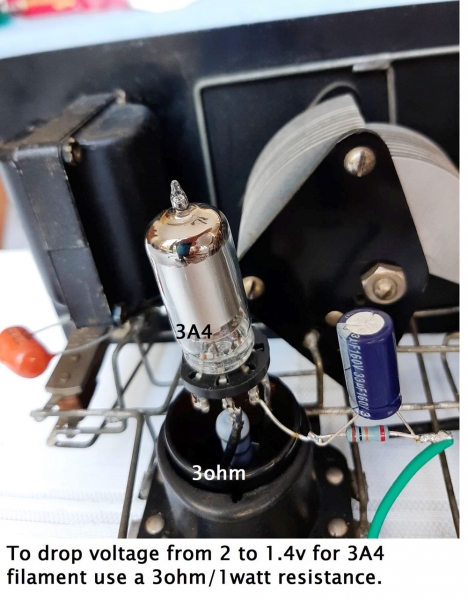
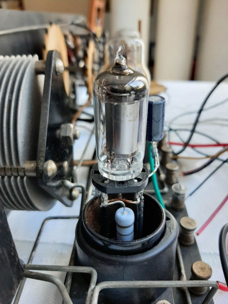
- Initially I used a 3V4 which I latter changed for a 3A4/DL93 in PENTODE connection in the output. I used a regular output transformer to couple the radio to an 8 ohm speaker! Results were just great!





Conclusions
- The reflex system works very well with Transformer coupling and with a combination of LRC and RC coupling.
- The combination of RC coupling of the audio signal from the detector stage to the RF stage (reflex mode), together with an LRC coupling between the first audio amplifier to the output audio stage in Pentode mode, produces a high quality speaker sound. The use of a bias voltage C- between 7.5 and 9 volts is imperative.
- The Reflex-Regenerative Circuit is very efficient, although at some frequencies the antenna tuning may be a bit broad.
- This 3 tube circuit compares very favorable to a 4 or even a 5 tube circuit.
Addendum The Power Supply
I Used the Power Supply that I made for the Reception Radio Corp. receiver. It is a regular 5 tube radio. I added a voltage divider controlled by a 60Kohm potentiometer in order to vary the voltage from 0 to about 22 volts. I used about 22 volts for the Crosley Trirdyn detector stage.
To operate the filaments I included another voltage divider controlled by a 15ohm/25 watts potentiometer. These additions worked very nicely. Please see picture.

Acknowledgements I want to thank my friend Raúl Urquilla-YS1UF- for making the high quality diagrams used in this article.
Add comment:
| Name: | ||
| code protection:* | ||
| email:* | ||

 Main
Main