Homemade SW Converter
Homemade SW Tube Converter
Several designs shortwave converters were invited by radio amateurs in 1930 - 1940 years. These converters have received very widespread and was very popular. The only downside, which is found in their design some hams - uncomfortable scale tuning. Ordinary limbs and vernier handles are uncomfortable "blind" scale. There are many shortwave radiostations, each of these stations is taken at two positions of the rotary knob, besides stations are not evenly distributed across the entire range, and grupped on some of its sectors. So, remembering those divisions of the scale on which the station can be heard, is very difficult, graduating at the same converter stations at such small size scales, which are obtained by using said pens - almost impossible.

Because of this, to converter has to be more convenient to handle, its scale should be much larger.
Homemade vernier mechanisms operate satisfactorily on long and medium wave, but on short wave their mechanical properties in most cases are not satisfactory. Therefore, in this construction used vernier scale from dual capacitors unit from "Radiofront" factory. This mechanism works satisfactorily and has a large scale, very convenient to the stations calibrate.

|

|
Homemade converter schematic
Converter schematic is similar to the industrial SW converters, for example SW Converter 1936.
But in the instance of the converter described were used widespread details. Variable capacitor from "Kazitskogo" factory has aluminum plates made by type capacitors, applied in 34 - EKL factory receivers. Structurally these capacitors is better than gilt - their plates are made of aluminum and are attached at the ends of combs. Consequently converters such capacitors are less prone to microphonics than converters with gilt brass plates, extremely elastic and therefore easily amenable to vibration. Unfortunately, the aluminum capacitors overlap is slightly worse than the gilt, but this shortcoming has to put up.
Inductor type high-frequency RF Dr 1. These reactors were commercially available everywhere. The filter consists of a resistor R3 and two capacitors C5 and C6. Capacitor C5 - 4 mkF, capacitance C6 - 2 mkF. Resistor R3 should be about 5000 Ohm. Resistance R1 approximately 1 Mohm, resistance R2 of about 8000 - 12000 Ohm.
Aerial capacitor C1 at a few pF capacitance has an interesting design. Piece of conductive wire for 20-25 mm wrapped with 3-4 layers of paper or adhesive tape. It is also possible to apply the cable isolation, etc. In general, the insulator layer should have a thickness of about 1 mm. On top of the insulator close, ie coil to a coil is wound in one layer of an enamel wire, with diameter of 0.8 - 2 mm, the length of the winding must be about 20 mm. Wire will serve as one plate of the antenna capacitor C1, and wound over the insulation layer of a thin wire - the other electrode.
The capacitor C3 must be equal to approximately 5000-10000 pF, capacitance C4 - 30 pF, capacitance C7 of 300 - 500 pF. Coils L1 and L2 are wound on a common frame with a diameter of 20 mm and a length of 20 mm, too. Coil L1 consists of 6 turns of wire 0.5-0.7 in enamel insulation, tightly wound coil to a coil. Feedback coil L2 is comprised of 8 turns of wire too 0.1-0.2 enamel insulation. This winding is divided into two sections by four turns each. These sections are arranged on either side of the tuning coil is about 2 mm from the coil. If, during the test of the converter to be clarified that the converter does not oscillate in the entire range, the feedback coil windings should be somewhat closer to the coil configuration.
Converter assembling
Converter mounted on the plywood panel of 6 - 8 mm. No screening in the converter is not used. This type of converters are not very sensitive to the capacitive effects, and provided a good grounding can work without screening.Accommodation details and their combination are shown in the circuit diagram.

Chassis dimensions: 220 x 160 mm. Height determined by the thickness biggest capacitors.
In both halves of the same drawing holes are indicated by the same numerals. In order to avoid cluttering the drawing, it is not shown rack which is fastened at the scale and the variable capacitor.
Power transformer is TS-26 from "LEMZO" factory, so it specially designed for use in converters.
Lamp socket is removed from the transformer and mounted near the transformer. If the kenotron panel leave on the transformer, the converter will be too high.
Arrangement of converter details does not play a particularly large role, and such placement can not strictly adhered to. Strengthening the variable capacitor is made by one of the metal racks and there is no difficulty. The illuminating scale lamp is powered by one winding of the converter with a lamp , i.e., on the bottom left of the winding.
Establishing
Establishing Converter is extremely easy. If all the items are applied are as mentioned above, the establishment of all reduced to establishing the correct direction of coil winding and a feedback to adjusting the distance between the windings of the feedback coil and the tuning coil. Wrong direction of turns of the coil feedback is recognized by complete silence converter (of course prior to assembly converter, check the serviceability of all its parts, and after the end of the assembly - the accuracy and reliability of all connections). If such silence converter will take place, the ends of the feedback coil should be interchanged. Thereafter correctly assembled converter will generate, but it is possible that it will generate only a part of the range.In this case, windings of the coil closer to the windings of the feedback coil configuration. Rapprochement is possible to produce almost direct touch between the turns of the windings of both ethics.
Rotating mechanism and the scale applied in the described converter allows accurate calibration of the device at the stations. Such grading can be done only by an experimental method - take on the converter station and the mark on the scale of those provisions of the pointer, which is obtained when tuning to a particular station. Defining fine-tune in a station, it is necessary to put a mark on the scale (eg point) and write notes about the station name. Initially, until the station will not be determined exactly, it is better to confine writing only station names, then it will be possible to calibrate the converter and the frequency or wavelength.
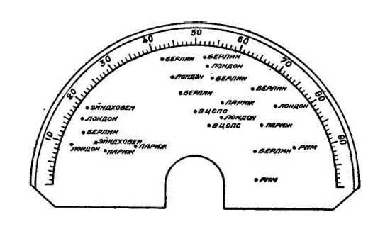
It is difficult to make such grading immediately, because the converter at different times of the day and even at the same time will be taken several "London" several "Berlin", etc. Understand, on what kind of wave works audible at the moment the London station, not always is easy.During calibration should be borne in mind that the settings on each station will fit two pointer position settings, which makes grading frequencies or waves. In fact, when receiving stations on the converter to better focus on the mark with the names. Wave frequency and the same calibration in the converter can be two and in each case it will be very difficult to determine on what scale should take a reading.
 Therefore, when applying for a converter station unknown should find both settings at her, and then by comparing the position of its configuration settings from the position of the double on other known stations, can be true impression of the length of its wave or its frequency. It should also be borne in mind that the grading shortwave converter is only correct if one absolutely certain that the long-wavelength tuning of the receiver, which is connected to a short-wave converter. Therefore, before you begin the calibration of the converter, it is necessary to determine which setting longwave receiver is the most favorable in terms of the absence of interference from local or general radio stations. When such a favorable adjustment of long-wave receiver and found her "quality" observations confirmed a few days - you can start grading converter. Appropriate setting longwave receiver should be noted accurately in the future accession to the receiver converter necessarily accurately tune in to this wave.
Add comment:
| Name: | ||
| code protection:* | ||
| email:* | ||
 Main
Main- About
- Antique radios
- Old Radio Collecting
-
Radio repair links
- Old Radios Troubleshooting Quick Guide
- Tube radios repair technology
- If you receive the parcel with an old radio
