A Tunable Loop Antenna
Indoor Loop Antenna
Author: Edgardo Castro Bruse| Author: EDGARDO CASTRO BRUSE |  |
San Salvador January 11, 2021
Introduction
All TRF receivers, especially those from the 20s need a good long wire aerial and a good ground pole. At the present time those two requirements are difficult for me to meet. So I decided to try a LOOP ANTENNA with a tuning system.Construction of the Antenna
The antenna was made by my friend and former student Mr. Enrique Lima YS1RM. The complete structure was made of one inche Inner Diameter PVC pipe and PVC T and X accessories. Then it was painted black.
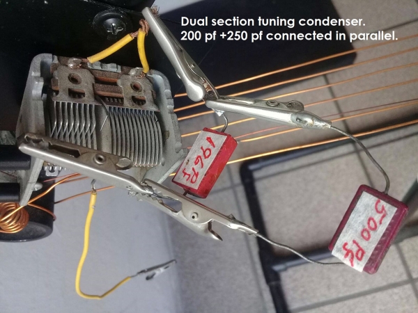
I added a tuning circuit consisting, of a two section variable capacitor of 425 pf total capacitance, connected in parallel with the loop. Also I provided two additional mica capacitors, one of 196 pf and another one of 500 pf. These capacitors may be individually paralleled to the variable capacitor in order to decrease the loop´s resonance frequency.
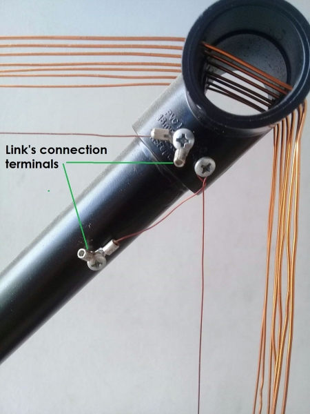
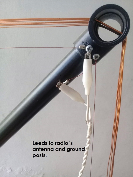
To couple the Loop Antenna to the radio I used a ONE TURN pick up loop.
To complete the loop's description I have prepared a set of pictures from z27 to z39.


Range of the Antenna
The calibration chart shown in pictures above is valid only for a particular radio receiver: "The Reception Radio Corp" of Philadelphia.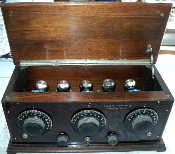
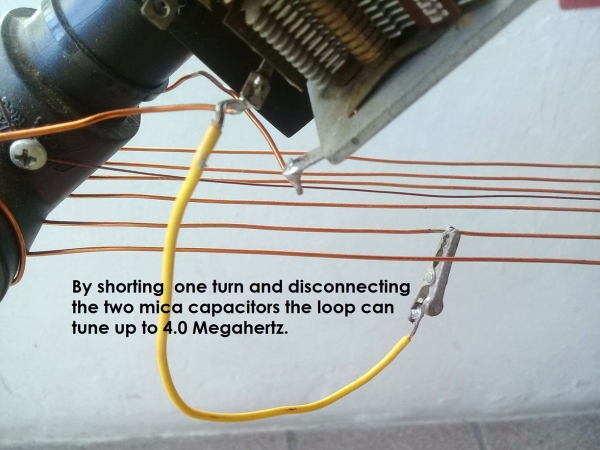
Nevertheless when used with another radio these markings will be only an approximate reference chart. With only the 196 pf capacitor connected in parallel with the variable capacitor, the Range of the antenna is from about 1160 KHz to about 700 KHz. Black Scale! With both, the 196 pf and the 500pf capacitors, paralleled to the variable capacitor the Range can go further down to about 520 KHz. Red Scale. To extend the range to about 4.0 MHz. Disconnect both mica capacitors and short circuit one turn of the loop.
Conclusions
- The antenna functions remarkable well in the BC band, from about 1160 to 520 KHz.
- By short circuiting one turn of the loop and using only the variable capacitor the range is increase to about 4 MHz.
- There is room for experimentation.
- The loop is absolutely very effective in cancelling noises of different natures. Specially man made noises that plagued the BC band.
- I encourage you to build one and sure you will enjoy it. Thank you for reading.
Add comment:
| Name: | ||
| code protection:* | ||
| email:* | ||

 Main
Main