KA-116 Short Wave Converter Replica
KA-116
Author: Edgardo Castro Bruse| Author: YS1ECB AUGUSTO EDGARDO CASTRO BRUSE Calle Loma Linda Residencial Loma Linda casa No. 4 Col. San Benito. San Salvador. El Salvador. |  |
San Salvador August 16, 2010
Introduction
In late October 2009, while visiting short wave converter, I came across the description of the KA-116, russian made, short wave converter. The design of this converter intrigued me, and at the same time it remainded me of a USA made converter called "The Sumariner", which diagram and photo were published in the October 1931 issue of "Radio News". I decided to contact the owner of this web page, and the first approach resulted in a fruitful friendship.
On Friday, November 13, 2009, I did get the KA-116 diagram that had the values of the resistors, and condensers, and with a large number of photos describing every angle of the original construction of the KA-116. From that day on, the project gravitated in my mind, and I was lucky to get more photos upon my request. Little by little I collected the parts, and once in a while, dedicated time to its construction. Finaly on the eve of August 1, 2010 I had the pleasure and satisfaction of tuning the first short wave stations on the Replica of the KA-116 Short Wave Converter!
Preparation of the chassis
Searching in my Junk Box (HUESERA in Spanish) I found an old and rusted chassis of a Heath Kit CC-1 Cathod Ray Tester. It still had the meter and a few parts in it.
This chassis had no large holes and had almost the perfect dimensions for the KA-116. So I decided to built this converter on this chassis.
The preparation of the chassis can be seen in the sequence of pictures shown below. (Click on images to enlarge)

|

|

|

|

|

|

|
KA-116: oscillator's coil & power transformer
Construction of the oscillator's coilThe coil was made after carefully analysing the photos of the original coil. From this photo the number of turns, and dimensions were estimated. The separation between windings was set to be 3mm.
- Coil form: Made of PVC; Outer diameter: 3,0 Cm.; Length: 4.5 Cm.
- Grid coil: 5 turns, of No.25 enameled wire. Each, turn separated from the next one, by a blue silk thread.
- Reaction coil: 7 turns, close wound of No.20 enameled wire. Placed between both halves of the grid coil.
- Note: The grid coil and the reaction coils are wound in the same direccion.
- Grid coil: 5 turns, of No.25 enameled wire. Each, turn separated from the next one, by a blue silk thread.

|

|

|
Results
When this coil was used with a variable condenser of 500 pF, its resonance varied, from about 4.5 MHz to about 13 MHz, as indicated by my Millen GDM. However when the converter was tested, the oscillator stopped working just below 7 MHz. To correct this problem 5 turns were added to the reaction coil. Because of the added distributed capacitance, the oscillator's range became 4.5 MHz ... 11.7 MHz. A perfect range!
In some cases this correction may not be needed, because the functioning of the oscillator, also depends on the type of tube being used, and the working voltages of the circuit. Therefore some experimentation may be needed.
Construction of the power transformer
This transformer was hand-made by my friend Josй Luis Argueta. It is wound on an old Philips iron core. Under actual use it produces the following voltages:
- 250--o--250 AC volts
- 3.94 AC Volts/3 ampers. Needed voltage 4.0 Volts AC!
- 2.81 AC Volts/2 ampers. Needed voltage 2.5 Volts AC!
- 3.94 AC Volts/3 ampers. Needed voltage 4.0 Volts AC!
This transformer can be seen below. (Click on images to enlarge)

|

|
Assembling the KA-116
The construction of the KA-116 may be appreciated in the sequence of photos shown below. (Click on images to enlarge)

|

|

|

|

|

|

|

|

|
Comparison and tests
Comments on the KA-116 circuitThe most important feature of this circuit is that the oscillator's tuned circuit is also the antenna's tuned circuit! This peculiar feature has the following advantages: economy, because you save one coil and one variable condenser.
Perfect tracking, because there are no circuits to track.
Single knob tuning, because there is only one circuit to tune. Note that the oscillator is operating contnuosly.
Sensitivity at no additional cost, because the oscillator tube also amplifies, to some degree, the signal coming from the antenna. Since this signal is applied to the oscillator's control grid, the mixing of signals take place right there.
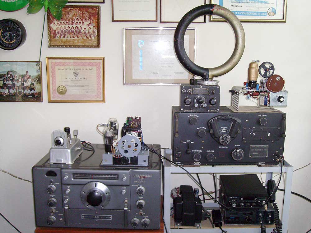 |
| KA-116 short wave converter in its operation position |
The same feature mentioned above has a few inherent problems:
- Repetition of signals, because every signal is heard at two different positions. Example: An incoming 5 MHz signal will produce an IF of 200 KHz, when the oscillator is at 4.8 MHz and when it is at 5.2 MHz, so every station is found twice in the dial.
- Reduced selectivity, because every signal is de-tuned 200 KHz if your IF is 200 KHz.
- Radiation, because the oscillator's signal is continuosly radiated into space due to the antenna coupling produced by the small antenna coupling condenser.
- Crossmodulation products, because there is no shielding at all of any of the sensitive elements like: the valve, the coil, the control grid lead, etc.
Practical evaluation: By experimenting with the KA-116 I concluded that its advantages outweight by far its disadvantages. It is exciting and practical to hear short wave stations with the KA-116 short wave converter!
I most say that THE LOWER THE IF IS CHOSEN THE BETTER THE KA-116 WILL PERFORM. I use a BC 348-Q tuned to 200 KHz as IF, and the results are just great.
To understand the russian designer when choosing this circuit that requiers a LOW IF, the reader must travel back to 1930 when the incipient superheterodyne BC receiver used 175 KHz IF and in USA the Airways Weather Band was from 150 KHz to 410 KHz. Most important in Europe they had (and still have) a real long wave BC band.
The "SUBMARINER" and the KA-116
 |
The main differences are that the "SUBMARINER" uses a triode type 27 and has regeneration control, while the KA-116 uses a pentode with no regeneration control.

The KA-116 with a salvadorean touch
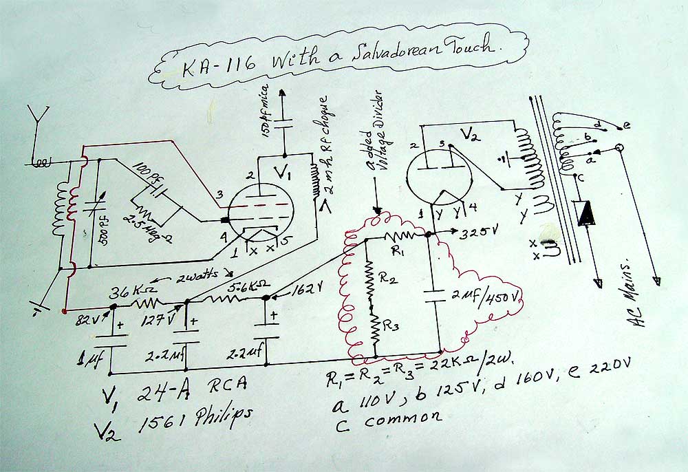 |
The only addition is a voltage divider. This was needed because the DC voltage provided by the power supply was 320 volts DC under very light load.
The voltage divider as well as the complete diagram including parts values and voltage readings are shown in the diagram.
Add comment:
| Name: | ||
| code protection:* | ||
| email:* | ||
 Main
Main- About
- Antique radios
- Old Radio Collecting
-
Radio repair links
- Old Radios Troubleshooting Quick Guide
- Tube radios repair technology
- If you receive the parcel with an old radio
