Articles
Mallory Bias Cells
 One of the most perplexing problems faced by the radio design engineer has been the method of obtaining bias for various tubes. Unless large by-pass condensers are used with a filter network, cathode bias, or bias derived from the voltage drop in the negative lead of the power supply system, has many disadvantages. Common impedance, and voltage fluctuations with signal in the power supply circuit causes a continuous variation of bias voltage.
The bias voltage variation is responsible for many undesirable effects, such as instability, loss of bass note amplification, and distortion. As previously explained, the by-passing efficiency of a condenser varies with the frequency. At the low frequencies where the by-passing action is most needed, the efficiency of the condensers is the lowest. Condensers of sufficient size to prevent objectionable bias variation are both bulky and expensive. Cathode bias has the further disadvantage of placing the cathode at a different potential from the heater, so that electronic emission from the heater will frequently cause an objectionable amount of hum.
 In the past the only alternative methods of obtaining bias were through the use of a separate "C" bias power supply, requiring a separate rectifier tube, choke and filter condensers, or by using a common "C" battery. It will be generally agreed that a "C" battery has little place in a modern AC receiver, transmitter, or PA amplifier as such batteries have a tendency to become noisy and develop high resistance with age, and frequently fail when most needed.
 Stated briefly what was needed was an independent source of "C" bias that was inexpensive, compact, absolutely quiet, and having a life equal to the other components of the circuit - the tubes, resistors, and condensers. It was unnecessary for the bias supply to furnish current or power because no appreciable grid current flows in an amplifier tube operated under Class "A" operating conditions.
After many years of research the problem was successfully solved by the design of the Mallory Grid Bias Cell. Over three million Mallory Bias Cells are now in use. They are standard original equipment in most modern receivers.
What is a bias cell?
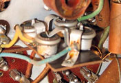
CHARACTERISTICS - 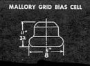 Physically, the bias cell is a small acorn-shaped device 5/8" in diameter and 11/32" deep. The black disc is the positive electrode, the metal container is the negative electrode.
VOLTAGE - Bias cells are produced in two types: the standard 1 volt cell, and the new 1,25 volt cell. The two types may be distinguished by the fact that the 1,25 volt cell has indentations or concave depressions in the electrodes, while the 1-volt type is smooth.
For experimental applications the choice between the two types of cells should be made on the basis of the voltage that is required. When making repairs on commercial receivers, replace with the type of cell that was used as original equipment.
CURRENT (DC) - The cell is strictly a potential, or voltage, cell and should not be used in circuits in which currents of over one microampere or .000001 ampere is drawn from the cell.
CURRENT (AC) - The characteristics of the cell are unaffected by superimposed AC as high as 360 microamperes of any frequency.
TEMPERATURE - The cells may be used in ambient temperatures from 40° below zero to 120°F. The voltage of the cell remains reasonably constant throughout this wide temperature range. It is recommended, however, that wherever possible the bias cells be placed in the coolest location.
HUMIDITY - The cell exhibits no change in characteristics when exposed to a relative humidity of 90% at 120°F.
IMPEDANCE - The bias cell is non-reactive at audio frequencies and the DC resistance ranges between 11,000 and 50,000 ohms.
NOISE - The cell does not cause the development of any noise.
Under no circumstances should the Mallory Grid Bias Cell be checked with an ordinary voltmeter, regardless of the sensitivity of the meter (ohms-per-volt rating). If for any reason it is desired to read the voltage of the cell, a vacuum tube voltmeter (VTVM) should be used which has at least a 10 megohms input impedance.
Precautions
To insure complete satisfaction from the use of the Mallory Bias Cells, the following simple precautions should be observed:
- Bias cells should not be used to bias oscillators, power output tubes, or amplifier tubes in which grid current may exist.
- The new 1,25 volt Mallory Bias Cells may be mounted in any position. The standard Mallory 1 volt bias cells may be mounted in any position except with the black electrode in a horizontal plane at the top of the cell.
- To avoid accidental short-circuiting of the cell, keep it in its envelope. Do not permit cells to be carried loose in a pocket with metal objects such as coins and keys.
- When soldering bakelite insulated holders use care not to over-heat connections or loose terminals will result.
- Many of the new model receivers and amplifiers are using 1,25 volt Mallory Bias Cells, mounted in wire spring-type clips. Should it be desired to replace these cells, care should be taken not to deform the clip, or bend it so far that inadequate contact pressure will be maintained on the electrodes. The wire clips can best be spread by using a special tool that is made for the purpose; lacking this, a pair of long-nose pliers can be employed if the outer faces of the jaws are notched slightly to prevent slipping.
Bias Cell Rejuvination
by Neil S.I assume that the cells are the standard "Mallory" style which looks like an upside down classic flying saucer. Examine the flat side which is a flat carbon disk and see if the rubber seal/insulator is still intact. It may be a bit perished around the opening, from exposure to the air etc. but it must be in fair condition where it is between the zinc case and the carbon disk. If so, you will need a #60 to #65 drill bit, an insulin syringe and a dab of clear RTV sealer. With the drill held in a holder like a small exact knife handle (so you have some `feel' for what's happening) carefully drill down through the carbon near the edge heading for the cup in the zinc. When you feel the drill break through the carbon disk, STOP! Below the carbon is an insulating separator and below that?
Fill the syringe with some distilled water and poke the needle carefully through the hole and the separator (it's soft like blotting paper or fabric) and inject a few drops of water below the separator. If water instantly comes out of the hole you are not into the space in the back. STOP. Go deeper. DO NOT inject too much water, we don't want it to start to come out of the hole since it will then be shorting from the back (-) to the carbon (+).
Once you have injected the few drops, wait a few minutes for it to soak in and then check from the zinc - to the carbon + with a VTVM or DVM and if all went well, the cell should have about 1.2 to 1.45 V showing. If it is now OK, then, with a tooth pick, apply a tiny spot of RTV into the hole to seal it. Keep the RTV off the carbon face, so it does not insulate the contact finger of the holder. If you still have 0 V then you will need to make an adapter to install a silver watch cell in place of the old one. Remember the silver cell must go in face down so the + is outward, and the edge of the cell must be insulated from the holder.
Add comment:
| Name: | ||
| code protection:* | ||
| email:* | ||
 Main
Main- About
- Antique radios
- Old Radio Collecting
-
Radio repair links
- Old Radios Troubleshooting Quick Guide
- Tube radios repair technology
- If you receive the parcel with an old radio
