Restoration methods
Repairing an Old American Radio
Author: Marc GraviereChecking and repairing power supply and filaments line

- The first step to repair an old radio is to check the filament of each tube. If one is open, all the line is out of order. So, first of all, take out each tube and check the filament with your ohmmeter.
If one is ruined, change the tube. - You also have to check the first capacitor inside the High Voltage(B+) circuit. It is often shorted and it is very dangerous for the rectifier tube.
- Don't forget to check the capacitors between AC line (B-) and the chassis and between AC line (B-) and the rectifier plate. It is very important for your security to work on a chassis which is insulated from the AC.
- You also have to check the AC cord. Sometimes it might be badly insulated. In that case, remove it and solder a new one.
Afterwards, you can try to plug in your set but keep your eyes opened: you might have to unplug it quickly if you see something burning inside!
Listen to the speaker to hear the hum and check the B+: B+ must be close to 100 Volts.
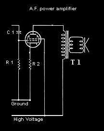
Checking and repairing A.F. power amplifier
 You have no sound (or a low level sound) when touching the command grid (G1) and no difference when changing the tube. The heater line is not open and the heater voltages are suitable for the tubes.
First, check High Voltage: it must be about 100 Volts. If H.V. correct but no H.V. on the plate, check the primary of T1. Plate voltage must be the same as power supply high voltage.
Secondly, check the cathode voltage and compare it with the command grid bias.
The G1 bias must be about 7 volts under the cathode voltage to induce a good current.
If the G1 voltage is too high, check the C1 capacitor. Sometimes it could be shorted and G1 should receive a part of the pre-amplifier plate voltage. In this case G1 should be positive and the tube should be locked or the sound very poor.
Sometimes, R1 could be open (or could have a very high value) and the result should be the same.
In most of American Radios, C1 is a part of a multi-capacitor. It's not easy to find these multi-capacitors today.
If the G1 bias is correct but the cathode voltage is not, check R2 (generally 270 ohms). If R2, R1, V G1, V G2, V plate are correct, but the cathode voltage is too low, the tube is probably dead; the current is too low to make a voltage drop through R2.
Checking and repairing A.F. pre-amplifier
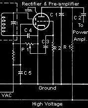 If your pre-amplifier does not work, and you have tried to change the tube, check the plate voltage first. If the high voltage is correct (100V) the pre-amplifier plate voltage must be about 40 volts.
If it is too low, check R1 and C1. C1 is a small value capacitor which just allows to drop high audio frequencies.
If C1 is shorted, the current through R1 is increased and the drop voltage is too high. R1 is a 470K resistor and sometimes, if the current has been too high too long, its value could have changed. The tube is a triode and the grid bias must be negative because the cathode is on ground. To induce a good current, the grid bias must be about -1 Volt.
If not, check the bias resistor R2; its value must be 10 Megohms.
Also check C3; if it is shorted, the grid bias is near 0 Volt and the tube is locked.
The potentiometer P1 is frequently responsible for the failure. It is often dirty and induces many cracklings in the speaker. In this case, the only solution is to use a cleaning spray.
Finding a failure in C4 or C5 is not frequent.
Checking and repairing I.F. amplifier
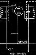 It's very easy to check this part of your radio. All you have to do is to check the plate voltage.
It must be close to the high voltage: 100 Volts.
The G2 voltage is the same than High Voltage.
The cathode is on ground.
The grid bias is at the same value as the VAC line (near 0 volt when a high level stations tuned on, negative when no station is tuned on), to increase the current through the tube.
Don't forget to check the capacitor between the VAC line and the ground. If it is shorted, the grid bias is always near 0 volt ans the receiver has a very low sensitivity.
Checking and repairing mixer stage
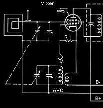 If the heater is OK, the only thing you have to do is to check the plate voltage and the screen voltage. On the plate you must find a value close to B+, and on the screen, the value is B+.
The oscillator grid resistor is a 22k for a 12BE6 tube but is different for another tube. If you have a scope you can check the oscillator on this grid.
From "American Old Radios"
Add comment:
| Name: | ||
| code protection:* | ||
| email:* | ||
 Main
Main- About
- Antique radios
- Old Radio Collecting
-
Radio repair links
- Old Radios Troubleshooting Quick Guide
- Tube radios repair technology
- If you receive the parcel with an old radio
