Atwater Kent model 40
Restoration of Atwater Kent model 40
Author: Edgardo Castro Bruse| Author: EDGARDO CASTRO BRUSE |  |
Introduction
I bought this radio from an eBay seller, at a good price, in the middle of 2015.
It called my attention its "Coffin" type, heavy metal case, and the fact that the radio looked intact, clean, and with all of its original tubes in place.
The radio had a rough trip from USA to El Salvador, as evidenced by the fact that the tuning knob came broken into several pieces.
Incredibly, all tubes were OK, and the box presented no damage.


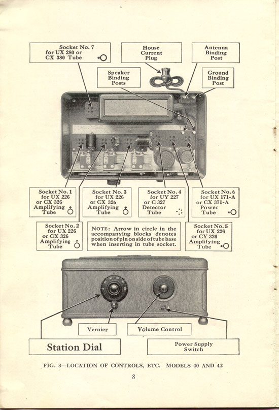
Description of the Radio
This is a 7 tube AC, TRF (tuned radio frequency) receiver made in 1928.
The antenna amplifier is aperiodic followed by two tuned RF amplifiers. The RF chain uses three type 26 tubes.
The detector has a 227 tube in a tuned, grid leak detector circuit.
The audio channel uses a type 26 tube, transformer coupled to a 171A audio output amplifier.
The PS uses a type 80 tube in a full wave circuit. Please see diagram and picture.

Restoration Process
A - Removal of Radio from Box. First, loosen up and remove the screws that hold the power supply to the bottom of the box.
Second, unscrew the front of the chassis from the front of the box, now carefully pull it out of the box and place it on the table top. Then lift the power supply and put it on the table top too. Please see pictures.


B - Initial Testing.
With the radio out of its box, I carefully inspected it. Then I connected it, by means of a variac, to the 117VAC line. In a time period of 30 minutes I brought the radio up to produce 45 volts DC at The B+ terminal. I found voltages at the Detector and 2nd AF stages, however there was no voltage at the 1st AF stage. I found that C14 was in short circuit and it was replaced by by a 10mf/450V capacitor.
I repeated the process and found that the voltage rose to 160V, but in a matter of about 8 minutes it dropped to 75 volts!
Conclusion: Power supply capacitors were too leaky and had to be replaced!
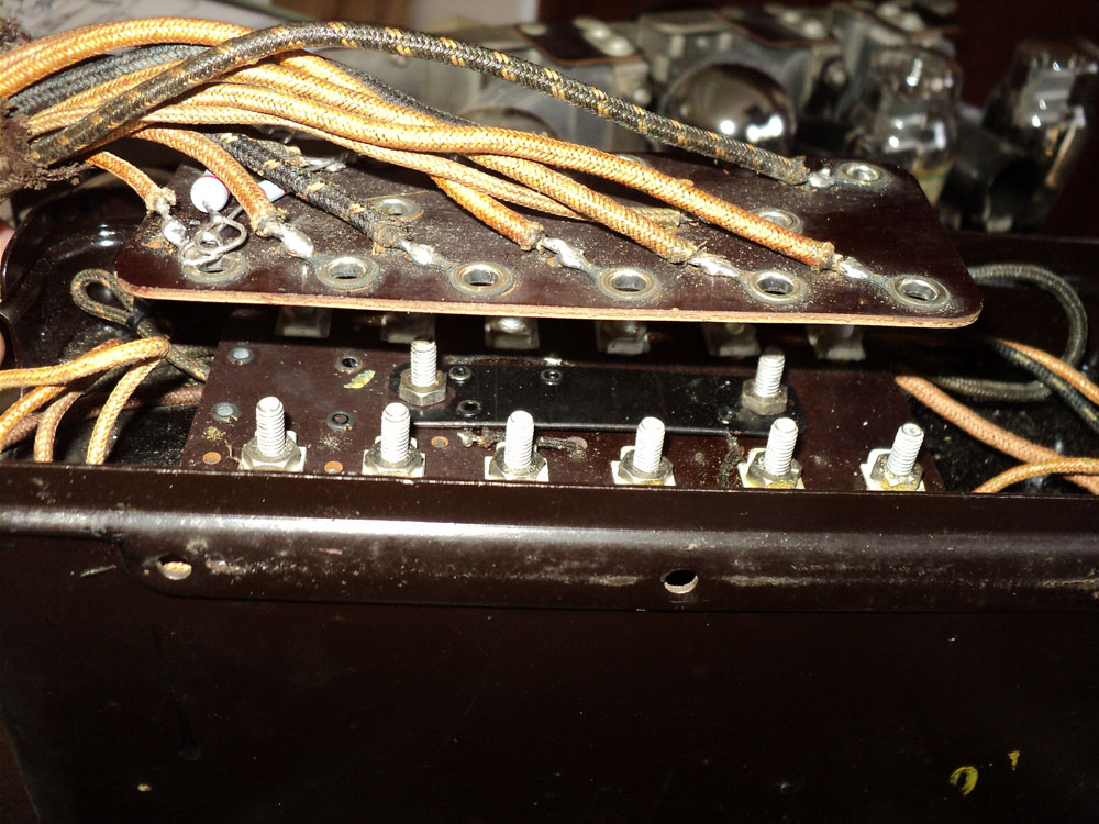
C - Reaching the DC Filter
All components of the power supply were immersed in a very hard black tar. To get to these components two fiber boards had to be removed. The first board had all the connection lugs. The second one had on its top side the negative bias resistances for the 2nd audio stage and the RF-1st audio stages and on its underside the filament resistances. All resistances checked OK! Please see pictures.


D - Identification of components of the DC filter
Once at the bottom, I identified the capacitors' leads and chokes by cutting the wires and tracing them to the corresponding capacitors and chokes. Please see pictures.


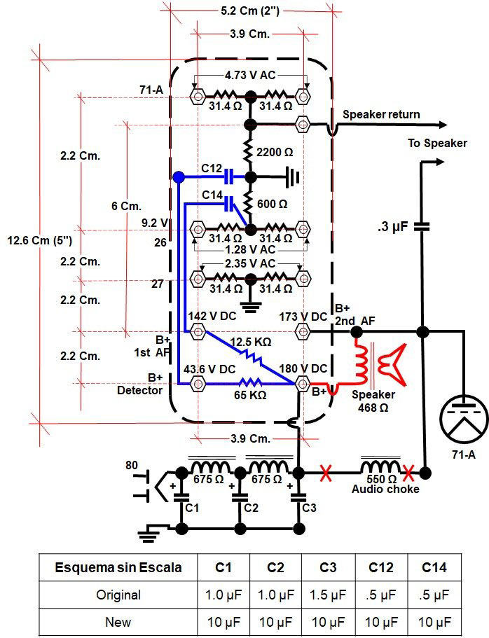
E - Summary
All of the efforts regarding the power supply repair work can be best summarized in the following diagram. This diagram was made by my friend Raúl Urquilla YS1UF. See diagram.
F - Replacement of volume control
Back in 2015, when the radio was repaired, I had to change the original 400 ohm wire volume control. I replaced it with a small drum 1Kohm logarithmic control. Now, that I had to change the AC switch, I also changed the volume control, because it became too noisy. This time I used a 1Kohm-large drum-logarithmic control and it works great! Please see pictures.


G - Replacement of Variable Capacitors Belts
When I assembled the radio in 2015, I stretched one of the belts, because incorrect manipulation, so to make it work I had to put a wedge to keep it stretched.
In May of this year, miraculously, I was able to buy both belts from an eBay seller. This time I installed them correctly! Please see pictures.


H - Last Repairs
The filament by pass capacitors and the RF by pass capacitor come in one metal box as shown in the picture. I decided to change the RF capacitor because it operates at high voltage. The filament capacitors are still operating well!
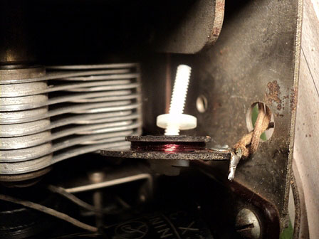
When the radio was tested it worked real well, but if you would tap on it, you would hear a scratchy noise. It took me time to discover that, this annoying noise was produced by a rusty screw that held the antenna choke to the chassis. To remedy it, I used a plastic screw with a plastic washer and nut. Please see pictures.


I - Conclusions
The Radio is surprisingly sensitive with good selectivity. It really is a pleasure to operate this single tuning control radio.
In my case I added a regular output transformer in order to use a normal 3.2-4 ohm speaker. Its 171-A output tube puts out an impressive loud and good quality sound! My most surprising result was that I connected a 400 ohm Philips speaker through a 10 mf non polarized condenser between the Speaker return and the Plate of the 171-A and the radio worked super well!
Add comment:
| Name: | ||
| code protection:* | ||
| email:* | ||
 Main
Main- About
- Antique radios
- Old Radio Collecting
-
Radio repair links
- Old Radios Troubleshooting Quick Guide
- Tube radios repair technology
- If you receive the parcel with an old radio
