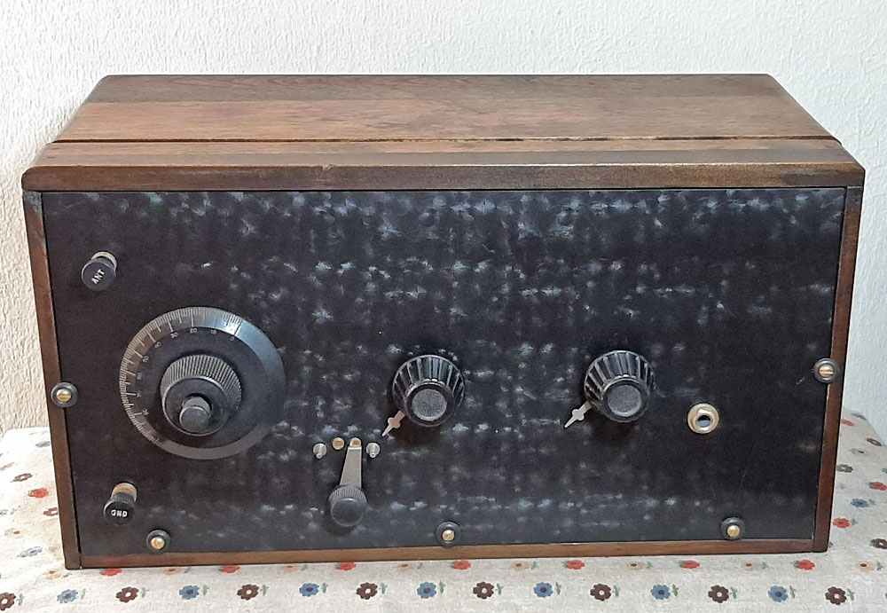
Stewart Radio Corp. Style 320
Stewart Radio Corp. Style 320
Author: Edgardo Castro Bruse| Author: EDGARDO CASTRO BRUSE |  |
Introduction
I bought this radio in January 2021.
It called my attention the excellent condition of the radio and the fact that it was a Three Tube Radio.
From the pictures I spotted a dark cylinder that I could not figure out. I asked the seller and he did not know either.
I thought it was a Stewart Warner Corp. Radio, but upon arrival I found out it was not! Also I discovered that the radio panel
had two large fractures. The fact that this was an intriguing radio prevailed over the front panel's problem!

What Kind of Radio is this One?
I traced the circuit carefully and made its diagram.
The fact that the Plate of the Detector's Stage was connected directly to the Antenna coil, and then to its Control Grid by means of the Grid Leak Resistance and its associated Condenser disturbed my mind.
I made an extensive web research and concluded that my radio was a unique commercial version of an ULTRA AUDION RECEIVER.

It is a very peculiar regenerative receiver.
It was studied by several radio designers like Lawrence Cockaday and a fellow called Marnikay. Also a number of Radio Magazines published articles on the Ultra Audion Receiver. A fascinating description of this radio can be found in radiomuseum.org
The Ultraaudion - Wireless Weekly 1927
How to Make an Ultra-Audion Receiver - Radio Age
ULTRA-AUDION — A name sometimes applied to the vacuum tube used in connection with beat reception for supplying local oscillations. In general, however, the name ultra-audion applies to a circuit for radio reception.

ULTRA-AUDION CIRCUIT — A type of circuit used for long wave radio reception which uses a form of regeneration, without calling for the introduction of auxiliary equipment in the circuit. A typical ultra-audion circuit is illustrated. It will be noticed that while one terminal of the secondary goes to the grid, the other terminal, which usually goes to the filament, in this case goes to the plate. Thus there is a direct plate-filament circuit which does not involve the plate and filament batteries in the usual manner.
Ultra Audion Features
It's most distinct feature is that there is a direct connection between the Detector's Plate and its Control Grid.
The regeneration path begins at the Detector's Plate, then to the Antenna Coil, and continues to the Grid Leak Resistance and its associated Condenser, and it ends at the Detector's Control Grid!
Therefore the easiest way to have SOME control of the regeneration is by varying the Filament Voltage.
This is the method used in my Stewart Radio Corp. Style 320
Another method to control the regeneration is to increase the grid leak resistance and to decrease the grid condenser:

General Restoration Process
The restoration of this radio was done in two parts. First the Cabinet's and Second the Electronics.Cabinet's Restoration
To give the reader a description of the process, including the damages produced during transportation, I will show three Sets of Pictures.
Set 1 eBay seller's pictures. Set 2 Damages upon arrival. Set 3 the repair process.


Arrival Pictures


Front Panel Restoration


Restoration of the Electronics
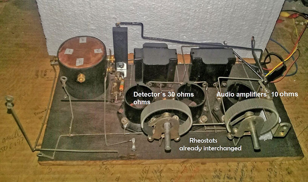
After visual inspection I proceeded to check the two inter-stage transformers. They checked OK!
Then I checked the Grid Leak Resistance. It was open! I replaced it with a 3.3 Mega ohm resistance.
It was evident that some of the wires dealing with the distribution of B+ voltage, B+ detector's voltage, B- and the Filament Voltage were missing.
At this point I decided to trace the circuit, in order to have its diagram. This diagram told me I had a radio I had never seen before: *AN ULTRA AUDION*
After completing the missing wiring, I found that the detector's rheostat was only 10 Ohms and the Audios' rheostat was 30 Ohms. This indicated to me that they had to be inter-changed.


Interchange of Rheostats
This process is self explanatory. Please see pictures.


Substitute Tubes for 01-A Tubes
Because I did not have the required 01-A tubes, I adapted some tubes I had in my Junk Box.They worked very well!


Pictures of the Radio after its Electrical Restoration:


Testing The Radio
I used a home-made power supply that provided 90V DC, 45V DC, 22.5V DC and 5.0V DC at 3 amperes.
First I tried this radio with a 5 meter long L shaped antenna and a ground connection provided by the mains home line. The results were modest sensitivity, and a regeneration difficult to control with the filament rheostat.
I also tried my Tuned Loop Antenna and the results were just a little bit better.
Improving the Radio
I wanted to keep the original circuit intact, as much as it could possible be.
Also wanted to have some control of the regeneration.
So I placed an estimated 1.5 mh RF Choke in parallel with a 10 K ohm rheostat between the Detector's Plate and the Antenna Coil.
I turned the radio ON and tuned to a station at 770 KHz (YSKL). I increased the detector's filament voltage until YSKL was heard, then I increased it even more until a vigorous oscillation was heard. At this point I began to reduce the resistance of the rheostat until the Audio Signal increased the most and the Oscillation was reduced to zero.
Eureka! it was working very well.
At this point I turned the radio OFF, and measure the resistance of the rheostat (2,5 K ohm). Then I connected a fixed 2,5 K ohm resistance in parallel with the Choke!
The radio works real well in the range of 720 to 970 KHz. For other ranges the Rheostat must be re-adjusted.
Please see picture. I include the diagram now showing the RF Choke and the 2,5 K ohm resistance.


Conclusions
- The Ultra Audion Circuit is a design that has puzzled the imagination of experimenters from the twenties to actual times.
- It is stimulating to experiment with this circuit, often times producing unexpected results.
- In my case this receiver, with the 1.5 mh choke and the 2,5 K ohm resistance in parallel, works real well in the 720 to 970 kHz range. Varying such resistance changes the range of stable operation.
- No other radio has intrigued me more than this one. And I continue to experiment with it.
- Finally I think that only Stewart Radio Corporation dared to commercialize radios using the Ultra Audion Circuit. I found some information leading to conclude that they made One Tube Radios, Two Tube Radios and Three Tube Radios, like the "Style 320". I have really enjoyed dealing with this radio.
 |
 |
Addendum
The unconventionality of the Ultra Audion Detector pushed me to investigate and to experiment with it.
- I found that the Ultra Audion Circuit is a variation of the Colpitts Oscillator.
- The best operating point is just before it begins to oscillate. This point is obtained by changing the filament voltage by means of a rheostat. Previously you most determine the best plate voltage for the detector tube you are using. This voltage is between 12 and 22.5 volts.
- The capacitor in parallel with the grid leak resistance does two things: a) couples the RF signal to the control grid of the detector, and b) DETERMINES THE AMOUT OF FEED BACK ENERGY (regeneration) FROM THE PLATE CIRCUIT TO THE GRID CIERCUIT OF THE DETECTOR!
- The choice of this capacitor depends mainly on the kind of tube used as a detector. Old tubes required more capacitance, modern tubes less capacitance.
The so called “soft tubes” like the Argon filled UV 200 required from 250 to 350 pf. The classical 01-A or 201-A and type 30 tubes from 150 to 250 pf. And modern tubes like the DL94 operating as a triode from 47 to 120 pf. In my case I decided for 47 pf. The smaller the grid capacitor the higher the plate voltage required for stable operation. The maximum voltage being 22.5 volts when a 01-A tube, and a 47pf with a grid leak resistance of 15 Meg. are used! I experimented THIS! - As in all regenerative receivers the grid leak resistance determines the operating point of the detector and its sensitivity. It is really worthwhile experimenting with values between 3 and 20 Meg. In my case with a DL94, operating as a triode Ultra Audion Detector, I used a 15 Meg grid leak resistance and a 47pf grid capacitor. The combination works real well

Audio Modifications
As a substitute for the 01-A, in the output stage, I first used a 3V4 in a triode connection circuit. It worked ok even without a C- voltage. I experimented connecting the 3V4 in pentode connection.
I used a screen grid dropping resistance of 33Kohms and a bypass capacitor of 22uf/160 volts.
I included a 9 volt battery to provide a negative 9 volts bias voltage to the grids of both audio tubes. This arrangement worked real well! With a very noticeable increase in volume!
I now present to you the modified diagram, and a picture that shows the C-bias battery of 9 volts. Please note that I kept the original Audion Detector as in the original radio. I used a 15 Meg grid-leak resistance and a 47 pf grid capacitor


Finally I encourage the reader to experiment with this interesting circuit and enjoy some interesting surprises!
Acknowledgements I wish to thank my friend Raúl Urquilla YS1UF for his continuous support, and for turning my Hand-made Diagrams into Computer-made Diagrams.
Add comment:
| Name: | ||
| code protection:* | ||
| email:* | ||
 Main
Main- About
- Antique radios
- Old Radio Collecting
-
Radio repair links
- Old Radios Troubleshooting Quick Guide
- Tube radios repair technology
- If you receive the parcel with an old radio
