Stewart-Warner 345 radio restoration
Stewart-Warner 345
Author: Edgardo Castro Bruse
| Author: YS1ECB AUGUSTO EDGARDO CASTRO BRUSE Calle Loma Linda Residencial Loma Linda casa No. 4 Col. San Benito. San Salvador. El Salvador. |  |
San Salvador , January 22 2012
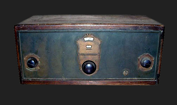
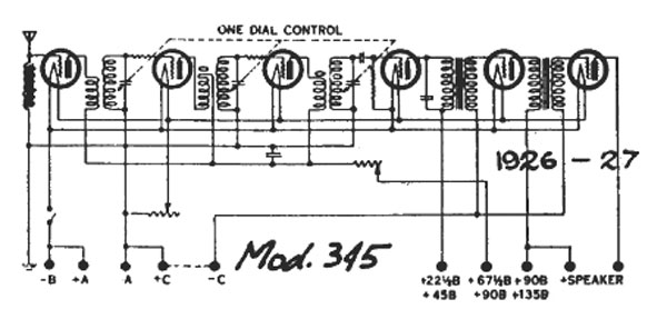
Stewart Warner model 345 battery operated receiver, circa 1926. It would have been one of the later battery operated radios as most makers began producting AC radios in the late 1920's. The Stewart-Warner 345 is a TRF receiver using six 01-A tubes. The first stage is an untuned (aperiodic) RF Stage, coupling the antenna to the radio. The second and third stages are tuned RF amplifiers feeding a tuned detector. Finally the radio has a two stage audio amplifier.
Disassembling the radio
The pictures shown are self explanatory of the process. Please click on images to enlarge.

|

|

|

|

|

|

|

|

|

|
Cabinet restoration
First, the cabinet was carefully sandpapered, and then all joints were reinforced with White glue. The bottom part was reinforced with metal flat corner braces. This procedure added sturdiness to the entire cabinet.Using a soft cloth, a light brown (almost transparent) coat of tint was applied as uniform as possible. Then I allowed it to dry for a day. Finally a layer of transparent varnish was applied given it a nice finish. To appreciate the process, please click on images to enlarge.

|

|

|

|

|

|

|

|

|

|
The front plate of the radio is made of painted steel. The ornament of the vernier dial and the the ornaments of the two controls at both ends of the front plate are made of brass.
The front plate was carefully washed with soap, and the brass ornaments were cleaned and polished using a high speed reuter. Please click on images to enlarge.

|

|

|

|
Repairing the Electronic Circuit
This process was a real challenge that will be described along this article.To begin with, the radio came with only three original tubes of the type 01-A. This meant that I had to make some adapters in order to use other tubes. I will describe these adapters at a later time.
Upon careful checking of the components I found the incredible surprise that all mica condensers were OK! All had a leakage of less than 20 µA. All control grid wire resistors, were also OK! The only resistor that was changed was the detector's grid leak resistance, which was replaced by a 2.2 M resistor.
Audio Transformers
The detector's audio transformer had the primary opened, but the secondary was OK! The inter-stage audio transformer had the primary OK!, but the secondary opened. To fix this situation I decided to use the winding that had continuity, (more than 1000 Ohms) as the plate winding in the detector stage, and also in the first audio stage.
The final result was that the inter-stage coupling was an RC and audio choke combination. The good thing of the RC and audio choke combination is that, in this case, we do not have to remove anything from the original circuit. We just add on a 470 K and a 220 K resistors. We also add on two 0.05 µF / 400 V coupling condensers. In further pictures of this radio you will see some leads disconnected from the transformers lugs. I left them this way simply, because I had already disconnected them.
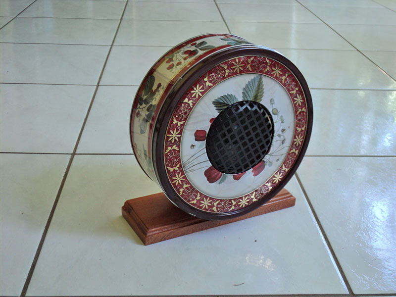
The radio uses a high impedance speaker, which is connected directly to the plate of the output tube and the B+. Since I did not have such a speaker, I used an old Philips output transformer to couple the output tube to a regular 5 inches 4 ohms Philips speaker.
Both, the speaker and the transformer are enclosed in a metal Christmas Cookies Box. This will also be describe at a later time.
All of the above procedures are shown in red ink on the original diagram obtained from Nostalgia Air. To see these procedures and the output transformer; please click on images to enlarge.

|

|

|

|
Tube Adapters to Test the Radio
I used two 3Q5 tubes to substitute for two missing 01-A, and one type 30 to substitute for one more 01-A. These tubes plus the three original 01-A tubes would complete the six tube set up used by the radio.The type 30 tube does not need an adaptor. It is just plugged into the socket, and to reduce the filament voltage from 5.0 V to 2.0 V, a 51 ohms / 1 watt resistance is connected in series with the filament lead under the chassis. To see the diagrams and pictures of the tube adapters used in this radio, please click on images to enlarge.

|
||

|

|

|

|

|

|
Power Supply Construction
According to the diagram this radio could operate with two sets of voltages.First: 135 volts for audio stages; 90 volts for RF stages; 45 volts for the detector and 5.0 volts for the filaments.
Second: 90 volts for audio stages; 67.5 volts for RF stages; 27.5volts for the detector and 5.0 volts for the filaments.
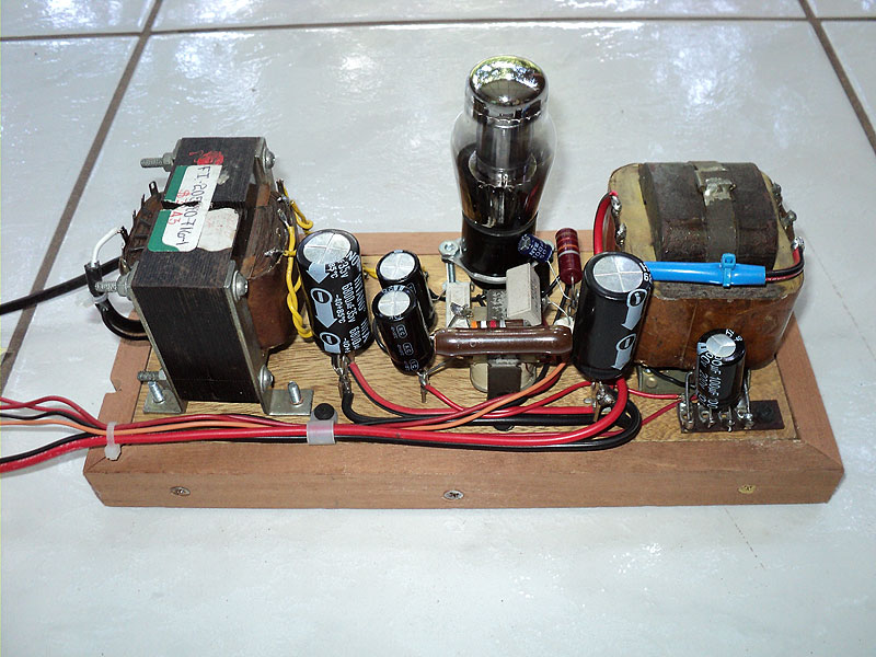
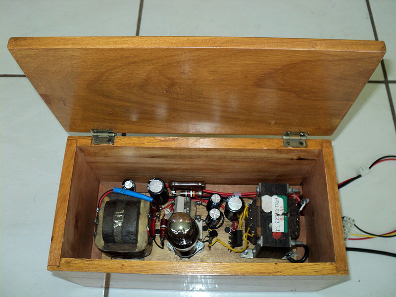
This power supply was designed using the parts that I had at home. Also I took into account the tubes characteristics.
Based on everything mentioned, my choice of voltages was as follows: 110 volts for audio stages 75 volts for RF stages; 36 volts for the detector and 5.0 volts for the filaments.
It is worth mentioning that the choke used to filter the filament voltage is a large autotransformer with a big iron core, discarded from the power supply of a tube TV set. This autotransformer provided multiple taps for experimentation, and a rather large inductance. This combination of factors resulted in a filament supply that provided hum-free operation of the radio receiver.
The bias voltage is provided by a 9 volt battery.
The diagram of the power supply is shown below.
 Please click on image to enlarge. |
||

|

|
|

|
|

|
Tests
To test the radio I connected a Philips speaker, by means of a Philips output transformer, to the radio's output. Then I plugged all tubes in their respective sockets, and connected a wire antenna to the radio. Voila! The radio was working perfectly!To get the maximum gain, I had to slightly adjust the three variable condensers, in order to get them to work in tandem. To do it, follow these steps:
- Tune a station around 1000KHz. This is close to the number 40 mark in the logging scale.
- Loosen each screw on each of the wheels of each variable condenser.
- Adjust each variable condenser to maximum volume of the incoming signal.
- Tighten back each of the screws.
These procedures complete the initial restoration of the 345.
To see the work done on the radio, from different angles, please click on images to enlarge.

|

|

|

|

|
"An Enlightening Error"
I was so delighted with the radio, that I did not put it into its cabinet right away. Instead I kept it as you see it in the pictures.This meant that I plugged and unplugged the cord from the outlet until, one day, one of the AC line wires broke off its connection point at the power transformer. I rushed myself to connect it back, and unfortunately I connected the wire to the wrong terminal. Burning the type 30 tube, and though the filaments of the 01-A tubes did NOT burn, the tubes were left without any emission. Lucky me, I learned how to rejuvenate them!!! This is why I called this an "enlightening error".
I will write, at a later time, a short article describing how I rejuvenated the 01-A.
Actual State of the Radio
Due to my mistake, now I had to provide four more tubes, and their corresponding adaptors. Searching in my tube box I found two new 1Q5 tubes, which are identical to the 3Q5, except for filament voltage which is 1.4 V at 0.1 A. This tube requires a 36 Om/1W resistor in series with its filament to drop the voltage from 5 V to 1.4 V. I used the closets value I had, a 39 Ohms/1W resistor.
 The other tube I used was the 1S4. This is a miniature 7 pin tube; to limit its gain, to the point of stable operation, I placed a 68 K resistor shunted with a 470 Pf mica condenser. This condenser is necessary in order to allow the RF to circulate through the primary of the 1st RF transformer.
The 3S4 adaptor was built, but it became unnecessary, because the gain of the 1S4 was sufficient to provide a real good signal reception with this receiver.
The antenna was connected at the RF point of the plate winding (PRIMARY) of the 1st RF transformer. All tubes, in their respective adaptors, were plugged in the sockets. The switch was turned on, and the radio came to life again! Basically this completes the restoration of the Stewart-Warner 345.
To see some pictures of the actual state of the radio with all of its tube adaptors in place, please click on images to enlarge.

|

|

|

|

|
Miscellaneous
Before anything else I would like to thank my friend German for posting this article in his website. Next my friend Aaron Weed (KC2NDA) for bringing the radio from New Paltz, New York, and my son Juan Enrrique for giving me the radio as birthday present.
The Speaker's Box
I would like to describe the making of the speaker box using a Christmas Cookies Box. The speaker is a 5 inches 4 Ohms Philips speaker. These pictures are self explanatory. Please click on images to enlarge.
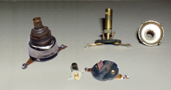
The ON/OFF Switch
The ON/Off Switch was opened up and carefully cleaned in order to get it to work properly.
Final Remarks
Working on this radio was really a learning procedure, and a test to validate various radio reception principles. I enjoyed very much this project, and I would like to use the 345 in conjunction with a Dresner Short Wave Converter. This new project should be of special interest, for the Dresner, though it is called a CONVERTER, It is really a one tube regenerative receiver that uses the power and the detector's tube of the BC receiver it operates with.
Before anything else I would like to thank my friend German for posting this article in his website. Next my friend Aaron Weed (KC2NDA) for bringing the radio from New Paltz, New York, and my son Juan Enrrique for giving me the radio as birthday present.
The Speaker's Box
I would like to describe the making of the speaker box using a Christmas Cookies Box. The speaker is a 5 inches 4 Ohms Philips speaker. These pictures are self explanatory. Please click on images to enlarge.

|

|

|

|
|
The ON/OFF Switch
The ON/Off Switch was opened up and carefully cleaned in order to get it to work properly.
Final Remarks
Working on this radio was really a learning procedure, and a test to validate various radio reception principles. I enjoyed very much this project, and I would like to use the 345 in conjunction with a Dresner Short Wave Converter. This new project should be of special interest, for the Dresner, though it is called a CONVERTER, It is really a one tube regenerative receiver that uses the power and the detector's tube of the BC receiver it operates with.
Add comment:
| Name: | ||
| code protection:* | ||
| email:* | ||
 Main
Main- About
- Antique radios
- Old Radio Collecting
-
Radio repair links
- Old Radios Troubleshooting Quick Guide
- Tube radios repair technology
- If you receive the parcel with an old radio
