Recovery technology
Tube Bias
 The main purpose of grid bias is to set the operating point of the valve near the centre of the straight (ie linear) portion of the characteristic curve when the valve is receiving no signal. The grid is set at a negative potential with respect to the valve's cathode.
A number of ways of achieving this result will be encountered in valve radios - Battery bias, Cathode bias and Back bias.
When an AC signal is applied to the valve via its grid the potential will swing above and below its biassed operating point. That is, the grid will become more or less negative (with respect to its cathode) due to the alternating nature of the signal.
As the signal swings postive so the grid becomes less negative and the valve passes more current. As the signal swings negative the grid becomes more negative and passes less current. Thus the incoming signal is reproduced at the anode or plate of the valve and passed on to the next stage.
It is important to maintain the correct initial bias so as to prevent the valve from going into the non linear part of its characteristic curve - if this occurs distortion will result.
 Battery Bias
In early battery sets the grid received its bias from a grid bias battery. The following diagram should help you visualise this.
In this diagram the battery valve has its grid returned via the grid return resisitor to a negative potential provided by a bias battery. The grid is thus suitably negative with respect to its cathode and the operating condition of the valve is set. Note that there is no voltage drop across the grid resistor as there is no current flowing through it.
Of course many battery valves will not have a cathode but will have one side of the filament connected to chassis.
Cathode Bias
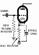
 In later AC sets cathode bias was commonly used with the current flowing through the cathode circuit being used to supply a voltage drop that could be used to bias the valve. This placed the cathode at above ground potential and with the grid being returned to ground it was therefore negative with respect to the cathode. Thus the required operating condition for the valve was set. The accompanying diagram should help you to visualise this.
Note here that the voltage drop across the cathode resistor depends on the current flowing through the valve. So to use a common example, a 6V6 valve might use a 250 Ohm resistor in its cathode circuit as it should draw 50 milliamps with a plate voltage of 250 Volts. Thus using V=I x R to calculate the voltage drop we get 0.05Amps x 250 Ohms = 12.5 Volts which is what the valve data books recommend for this valve.
Back Bias
In some sets you will come across a system known as "back bias". Here the centre tap of the HT secondary of the power transformer is returned to chassis via a resistor. The grid of the output valve is returned to the centre tap while the valve's cathode is connected direct to chassis. Thus the grid is at a negative potential with respect to the cathode. Here the voltage drop across this center tap resistor is equal to the required negative bias.
Note that the current drain flowing through this centre tap resistor is equal to the total DC current drawn by the all the valves in the set and this will need to be taken into account when calculating its value and power rating. To eliminate all hum from the set ensure that an electrolytic capacitor is connected in parallel with this resistor.
 (Positive terminal to chassis of course as it is postive with respect to centre tap) See the accompanying diagram.
Note here that two valves are being biassed by the back bias resistor. This is a useful feature of the system in that where a number of valves require biassing components can be saved. To calculate the value of a back bais resistor one needs to take the total current drawn by set into consideration. So for example in a set that draws a total current of 80 ma, the resistor would need to be 12.5V (the bias voltage neede for the 6V6 valve) divided by 80ma(the current drawn by the set). This equals 156.25 Ohms. The nearest commonly available value here is probably 175 Ohms. Remember to provide a resistor that will be able to handle the power dissipation needed - normally a 5 Watt resisitor will do nicely.
Note also that with a back bias arrangement the negative terminal of the first filter electrolytic MUST be connected to centre tap of the HT secondary and NOT chassis!
Add comment:
| Name: | ||
| code protection:* | ||
| email:* | ||

 Main
Main