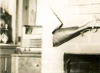
Philco radio, model 42-350
Philco radio. Model 42-350 (1942)
 Model 42-350 is a seven (7) tube superheterodyne radio designed for reception of standard, shortwave and Frequency Modulation broadcast stations, and the sound of a television program tuned in by special Philco Television Radios. The radio Incorporates six electric push-buttons for automatically tuning five stations in the standard broadcasting band.
Philco built-in:
- low impedance loop aerial for reception of standard and short-wave broad-cast stations;
- separate Automatic Built-in FM Aerial for reception of Frequency Modulation stations;
- three tuning ranges;
- two Intermediate frequency stages;
- tone control;
- illuminated band indicator;
- audio bass frequency compensation In the volume control circuit, and a peptode audio output.
| Manufacturer/Brand: | Philco, Philadelphia Stg. Batt. Co.; USA |
| Year: | 1941 / 1942 |
| Principle: | Super-Heterodyne (Super in general); |
| Intermediate frequency: | Standard Tuning, 455 KHz; FM channel. 4,3 MHz; |
| Valves / Tubes: | XXL, oscillator; XXL, converter; 7V7, 1st IF; 7V7, 2nd IF; XXFM, 2nd detector-lst audio; 7B5, audio output, and a 7Y4 rectifier. |
| Wave bands: | Broadcast, Short Wave plus FM |
| Frequency tuning ranges: | 540 to 1720 KHz; 9 to 15 MHz and 42 to 50 MHz (FM). |
| Loudspeaker: | Electro Magnetic Dynamic LS (moving-coil with field excitation coil) |
| Power supply: | 115 volts, 60 Hz AC. This model can also be operated on 25 Hz current. To do this it is necessary to replace the power transformer as indicated in the parts list for 25 Hz operation. |
| Power consumption: | 50 W |
| Audio output: | 1,5 W |
| Material: | Wooden case |
| Dimensions (WHD): | 18.5 x 11 x 10.5 inch / 470 x 279 x 267 mm |
The built-in aerial system is designed to operate without an outside aerial or ground and to give exceptionally high receiving performance of stations in the standard, shortwave, or FM bands. To operate the radio In steel reinforced buildings and other shielded locations where signal strength is weak, an external aerial is recommended.
The slide-rule type dial indicates three bands: the normal AM band, a shortwave band from 9.0 to 15.5 megahertz, and an FM band. The radio is one of the first Philco that come out with the FM "channel numbers" on it and is also short wave and public services, Amateur and of course standard broadcast.
FM band with "FM call numbers" labeled from 21-99. Those were the official FM channel numbers as specified by the FCC in 1941. The numbers 21 through 99 correspond to the frequency with the 4 and the decimal point deleted (i.e., 421 through 499). The FCC assigned call signs that had the customary W or K, the 2-digit channel number, and one or two letters indicating the city. Since Philco didn't sell FM sets until after this scheme was announced, they (and some other manufacturers) decided to use the channel numbers on the dial instead of markings in MHz.
Companies like GE and Zenith that had already been selling FM radios (there were a few experimental stations on the air) continued to use the MHz markings. The FCC dropped the special call sign system in 1944, at the same time that it permitted co-owned AM, FM and TV stations to use the same call letters...
Notes: [by Edgardo Castro Bruse]
Philco 42-350 uses the old FM band that goes from 42 MHz to 50 MHz. It is relatively easy to receive, more or less satisfactory, some of the stations in the modern 88 MHz to 108 MHz by simply detuning the local oscillator so that its second harmonic together with an incomming signal of the modern FM band produce an IF frequency of 4.3 MHz which is the IF frequency of the FM IF (Intermediate Frequency) transformers in this radio.
The electric push-button tuning mechanism consists of six (6) push-buttons. Five of the push-buttons are used for selecting standard broadcast stations, and one for the power control (ON-OFF).
Viewing the front of the cabinet from left to right the first push-button is the power control (ON-OFF), the next five push-buttons for tuning standard broadcast stations.
When setting up stations on the push-buttons the lowest frequency station is set up in the second push-button from the left and and the remaining stations according to increasing frequency in the next four push-buttons. These push-buttons are adjusted by the padders located on the rear of the chassis.
The second push-button from the left can also be adjusted for reception of the sound channel of a television program received by special Philco television radios. This push-button may also be used in conjunction with a Philco Wireless Record Player.

|

|

|

|

|

|

|

|

|

|
Comments: Comments: Comments: Add comment:
| Name: | ||
| code protection:* | ||
| email:* | ||


 Main
Main