Babcock Preselector model P2A DX'er overview
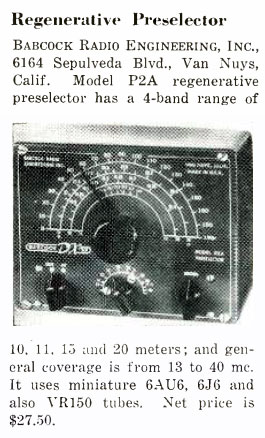
Regenerative Preselector
Author: Edgardo Castro Bruse| Author: EDGARDO CASTRO BRUSE |  |
San Salvador, September 5, 2019

|
|
This preselector was given to me by my Mentor Dr. Manuel Cader in 1963. It has been in operation since 1963 until present times. I found no information on this preselector, so I want to share what I have done.
I made the diagram directly from the chassis. The nominal values of resistances in the circuit are all within tolerance, except the 390 ohm/2 watt resistance, which measured 550 ohms. Since the preselector works real well, as it is, I did not change it.

Condensers C1, C2, C3, and C4 were not measured, so, I wrote in the diagram values that I considered appropriate.
All voltages were measured in actual operation of the P2A DX’er at 17.05 Mc. At present my Power Supply produces: B+ 160 VDC and 6.3 VAC. The actual current consumption is only 20 ma. Including the drain current of the VR150.!! Over the years I have used voltages B+ from 160 up to 300 V. To do this I have changed the 350 ohm/2watt resistance to the correct value for the VR150 to work properly.
I do hope you enjoy the P2A DX’er as I do.


Add comment:
| Name: | ||
| code protection:* | ||
| email:* | ||
 Main
Main- About
- Antique radios
- Old Radio Collecting
-
Radio repair links
- Old Radios Troubleshooting Quick Guide
- Tube radios repair technology
- If you receive the parcel with an old radio
